™
PROFET + 24V
BTT6200-4ESA
Diagnostic functions
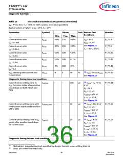
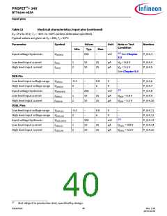
Table 10
Electrical characteristics: Diagnostics (continued)
VS = 8 V to 36 V, TJ = -40°C to 150°C (unless otherwise specified).
Typical values are given at VS = 28 V, TJ = 25°C
Parameter
Symbol
Values
Typ.
Unit Note or Test
Condition
Number
Min.
Max.
Current sense ratio
IL0 = 10 mA
kILIS0
kILIS1
kILIS2
kILIS3
kILIS4
ΔkILIS
-50% 330
-40% 300
-15% 300
-11% 300
+50%
VIN = 4.5 V
VDEN = 4.5 V
See Figure 21
TJ = -40°C; 150°C
P_7.5.8
P_7.5.9
P_7.5.10
P_7.5.11
P_7.5.12
Current sense ratio
IL1 = 0.05 A
+40%
+15%
+11%
+9%
+8
Current sense ratio
IL2 = 0.2 A
Current sense ratio
IL3 = 0.5 A
Current sense ratio
IL4 = 1 A
-9%
-8
300
0
23)
kILIS derating with current and
%
k
versus kILIS2 P_7.5.17
ILIS3
temperature
See Figure 22
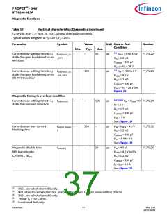
Diagnostic timing in normal condition
23)
Current sense settling time to
kILIS function stable aꢀer positive
input slope on both INput and
DEN
tsIS(ON)
–
–
150
µs
V
= VIN = 0 to
P_7.5.18
DEN
4.5 V
VS = 28 V
RIS = 1.2 kΩ
CSENSE < 100 pF
IL = IL3 = 0.5 A
See Figure 23
22)
Current sense settling time with tsIS(ON_DEN)
load current stable and transition
of the DEN
–
–
–
–
10
15
µs
µs
V
= 0 to 4.5 V
P_7.5.19
P_7.5.20
DEN
RIS = 1.2 kΩ
CSENSE < 100 pF
IL = IL3 = 0.5 A
See Figure 23
22)
Current sense settling time to IIS tsIS(LC)
stable aꢀer positive input slope
on current load
V
= 4.5 V
DEN
RIS = 1.2 kΩ
CSENSE < 100 pF
IL = IL2 = 0.2 A to
IL = L3
I = 0.5 A
See Figure 23
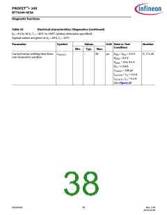
Diagnostic timing in open load condition
23
Not subject to production test, specified by design. Current sense settling time to
DSEL pin select channel 0 only.
22
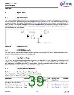
Datasheet
36
Rev. 1.00
2019-03-09

 INFINEON [ Infineon ]