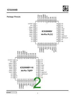
ICS2008B
The SMPTE Status Register is a read only register which
contains video and LTC status.
the field and frame from the selected video input. The even/
odd fields are identified by a 1/0 in bit 6. Bit 7, FRAME, is valid
for PAL video after line 6. Bit 6, FIELD, is valid after line 5 in
NTSC mode or line 2 in PAL mode.
7
6
5
4
3
2
1
0
SMPTE1
SMPTE Status Register
The SMPTE2 register is the register which points to the 57
indirect registers. When reading or writing an indirect register,
the value in theADDRESS pointer, SMPTE2 bits 5 to 0, is the
address of the register accessed through SMPTE3. If the
AUTOINC bit is set to one, at the end of an access cycle to
SMPTE3,ADDRESS will automatically increment. Otherwise,
ADDRESS holds its value.
FRAMEIN (input = 1-high, 0-low)
CLICK (input = 1-high, 0-low)
LTCLOCK (1-locked, 0-not locked)
CODEDIR (1-bkwd, 0-fwd)
Reserved
VLOCK (1-locked, 0-not locked)
FIELD
FRAME (PAL only)
7
6
5
4
3
2
1
0
SMPTE2
FRAMEIN — This bit indicates the state of the FRAME
input pin. It is used as an alternate source for B/A frame
status. This is useful when the quality of the video signal is
not good enough to extract the B/A frame status.
Indirect Address Register
ADDRESS
Reserved
AUTOINC (1-increment, 0-hold)
CLICK — This bit indicates the state of the CLICK input
pin. It can be used as a synchronization source for the LTC
transmitter.
SMPTE3 is the data register through which all of the indirect
registers are accessed. The address for a given register must
first be set in SMPTE2 before accessing that register.
LTCLOCK — When a valid forward or backward LTC sync
pattern is detected, this bit is set to one. It is reset to zero when
an expected LTC sync pattern is missed or an invalid LTC bit
is detected.
7
6
5
4
3
2
1
0
SMPTE3
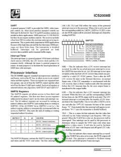
CODEDIR — The code direction bit works in conjunction
with the LTCLOCK bit. When the LTCLOCK bit is set to one,
the CODEDIR bit is valid. Otherwise, it is not. See the table
below.
Indirect Address Register
Indirect Registers
LTCLOCKCODEDIR LTC RECEIVER STATUS
The following describes the functions controlled by the
indirect registers. A map of the indirect registers follows this
section, on page 11.
0
1
1
X
0
Looking for SYNC pattern
Receiving LTC (FORWARD)
Receiving LTC (BACKWARD)
LTC Read Registers IR0-IR7 (read-only)
1
These read only registers contain the LTC data as received.
Both forward and backward frames are stored with LTC bit 0
in the LSB of IR0 and LTC bit 63 in the MSB of IR7.
VLOCK — This is a hardware driven bit which indicates that
genlock has been achieved with the selected video SYNC
source.
LTC Write Registers IR8-IRF
These registers contain the data to be sent by the LTC trans-
mitter. The LSB of IR8 is sent as LTC bit 0, and the MSB of
IRF is sent as LTC bit 63. The data is transmitted as it is stored
in IR8-IRF.
FRAME & FIELD — The hardware SYNC separator detects
ICS2008B
6

 IDT [ INTEGRATED DEVICE TECHNOLOGY ]