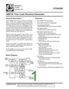
ICS2008B
Functional Description
Video Output
The video output combines the selected video input with the
outputs from the VITC generator and the character generator.
It can be a composite or an S-Video output as selected by the
SVID bit in the SMPTE control registers.
The following is a functional description of the hardware regis-
ters in the ICS2008B chip. It also describes how those
registers can be utilized by the software to facilitate specific
application services.
VITC code is generated from data in the VITC generator
buffer and output during the selected line time(s). The CRC
and synchronizing bits are automatically generated by the
VITC generator, but all of the data fields are sent directly from
the buffer with no modification.
Hardware Environments
The ICS2008B operates as a peripheral to a processor such as
a PC or a single chip microprocessor. Many of the real time
requirements are satisfied by double buffering both incoming
and outgoing time codes.
A character generator is provided to insert the time code in a
burn-in window which overlays the incoming video. The ver-
tical and horizontal position of the burn-in window is
programmable.
LTC Input
LTCIN is a differential analog input feeding a comparator
with hysteresis. It requires capacitive coupling to the LTC
source. The output of the comparator goes to the LTC re-
ceiver, which is capable of receiving LTC in a forward or
SMPTE SYNC Sources
th
A time code generator must have a SYNC input from a stable
source in order to position the LTC code properly on a audio
track of video tape or film. Three SYNC sources, video, click
input, and free running, are available. In the case of a video
tape, LTC code must start within plus or minus one line of the
beginning of line 5. This requires “Genlocking” to the incom-
ing video. The video timing section locks to the video’s
horizontal and vertical SYNC signal and generates a SMPTE
SYNC. If some external SYNC source is available it can be
input on the CLICK input. Otherwise, a free running SMPTE
SYNC is generated from the oscillator at the selected frame
rate.
backward direction at a rate from 1/30 to 80X nominal
frame rates. The incoming LTC data is sampled with a phase-
locked clock and loaded into the receive buffer following the
receipt of a valid LTC SYNC pattern. When a complete frame
has been received, an interrupt is generated.
LTC Output
The LTC output can be analog or digital. When set up as an
analog output, it can drive a high impedance load.
The LTC generator outputs a LTC frame at the selected frame
rate, such as 24 Hz, 25 Hz, 29.97 Hz or 30 Hz, and starts the
frame based on a start time generated by the selected LTC
SYNC source.
Video Timing Generator
The video timing generator is “Genlocked” to the video
input’s SYNC separator. It extracts NTSC or PAL timing in-
formation from the video input and generates line and pixel
rate timing for the VITC receiver, VITC generator, LTC gen-
The output edge rate is programmable for SMPTE code (25
µsec) and EBU code (50 µsec) rise and fall times.
Video Inputs
There are two sets of video inputs. In a composite NTSC or erator and character generator. If no video input is present, it
PAL system, the Y input is the only one used. It is capacitively generates free running timing.
coupled to the source. In S-Video systems, capacitively couple
Overlay Character Generator
Y and C to their respective sources. Proper termination of the
source should be observed. Unused inputs may be left open.
It is sometimes desirable to display the time code on a video
display along with the picture. A character generator is pro-
One of the two video sources is selected by the VIDSEL bit in
vided for that purpose. The time code display, or burn-in
the SMPTE control registers as the video SYNC source. Inter-
window, can be positioned anywhere on the screen. It can be
nal timers are synchronized with the incoming video to extract
displayed in two sizes with white or black characters on a
timing information used to receive and generate VITC.
black, white or live video background.
The VITC receiver samples the incoming video looking for a
valid VITC code on selected scan lines. When a valid code is
received it is written to a VITC receive buffer. More than one
line can contain VITC code, and the codes can be different. For
this reason, VITC codes from selected lines of a frame are writ-
ten to separate VITC buffers.
ICS2008B
4

 IDT [ INTEGRATED DEVICE TECHNOLOGY ]