ICS2008B
UART
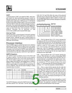
LRI, LXI, VLI and TMI reflect the status of the potential
interrupt sources to the processor. When a bit is set to one and
the corresponding enable bit, LRIEN, LXIEN or VLIEN, is also
set, the INTR output will be activated. Interrupts are cleared by
reading SMPTE0.
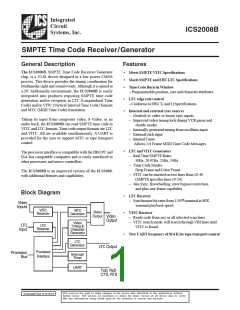
A general purpose UART is provided for MIDI, video trans-
port control, etc. Most serial interface transport controls use
9600 and 38.4K BAUD. The CTS and RTS modem controls are
needed in these applications. MIDI ports use 31.25K BAUD,
but they do not require modem controls. The receiver includes
a four byte FIFO to reduce the real time interrupt servicing re-
quirements. This is particularly important in MIDI applications
because of the high data rate and the fact that many MIDI mes-
sages are three bytes long. The transmitter is doubled
buffered. Interrupts can be generated on both
receiver data available and/or transmit buffer empty.
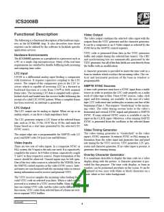
7
6
5
4
3
2
1
0
SMPTE0
Interrupt Control/Status
LRI (LTC RCV Interrupt)
LXI (LTC XMT Interrupt)
VLI (Video Line Interrupt)
LRIEN (1-enable, 0-disable)
LXIEN (1-enable, 0-disable)
VLIEN (1-enable, 0-disable)
TMI (Timer Interrupt)
Interrupt Timer
The interrupt timer is a general purpose 10 bit timer with three
clock sources (100 kHz, the LTC receive clock and the LTC
transmit clock). Although the timer is general purpose in
nature, its main purpose is to facilitate the timed generation of
MIDI time code messages.
TMIEN (1-enable, 0-disable)
LRI — This bit indicates that a LTC receive interrupt has
occurred. In order for an actual processor interrupt to occur,
the LRIEN bit must also be set. An LRI interrupt occurs upon
reception of the last byte of LTC receive data which was pre-
Processor Interface
The ICS2008B supports standard microprocessor interfaces
and busses, such as the PC bus, to allow access to six control/
status and data registers. These six registers are organized into
two groups, one set of four for SMPTE control and the other
set of two for direct UART port control. Each set of registers is
selected with its own chip select, SMPTECS* and UARTCS.*
th
ceded by a valid LTC SYNC pattern. That is after the 64
LTC receive bit time in the forward direction. At normal
frame rates, if the LTC transmitter is synchronized with the
LTC receiver, there is about 3 milliseconds after this interrupt
before the LTC transmit data for the next output frame is
transferred to the output buffer.
SMPTE Registers
LXI — This bit indicates that a LTC transmit interrupt has
occurred. When this bit is set, and the corresponding LXIEN
bit has been set, the INTR output will be activated. The LTC
transmit interrupt is activated after the transfer of LTC trans-
mit data to the output buffer. This occurs after LTXEN is set to
The SMPTE register set allows access to four direct and
64 indirect registers. The first two direct access registers
addressed at locations 0 and 1 are for status and interrupt con-
trol. The 64 indirect registers are accessed by writing an
indirect address into SMPTE2 and reading from or writing to
SMPTE3. If the AUTOINC bit in SMPTE2 is set to 1, the
indirect register address is automatically incremented after an
access to SMPTE3. This eases the task of reading or writing
sequential indirect locations.
nd
one and after the 72 LTC transmits bit time of the current
frame, “N.” Data loaded after this interrupt will appear in out-
put frame “N+2” since the transmitter is double buffered.
VLI — This is a status bit that indicates that the video line
selected via the Video Interrupt Line Register, VR9, has
passed. When the VLIEN bit is also set, the processor will be
interrupted. This interrupt can be used by the processor to
determine when to sample the VITC time code when time
locked to a video source. It will also be used to facilitate
detection of LTC time code dropout and off speed LTC code,
e.g. shuttling operations.
S M P TE C S *
A1
0
A0
0
R E G IS TE R
0
0
0
0
SM PTE0 -InterruptC ontrol/Status
SM PTE1 -SM PTE Status
SM PTE2 -IndirectAddress Register
SM PTE3 -IndirectRegisterD ata
0
1
1
0
1
1
TMI — This bit indicates that a timer interrupt has occurred.
When the TMIEN bit is also set to a one, the INTR output will
be activated. This interrupt is intended to facilitate timing
MIDI clocks and MIDI Quarter Frame messages.
The SMPTE0 Register contains the SMPTE interrupt controls
and status and the VITC read status. The four interrupt bits,
ICS2008B
5

 IDT [ INTEGRATED DEVICE TECHNOLOGY ]