ICS2008B
complete LTC frames are transmitted. The data to be sent by
the LTC transmitter should be loaded into the associated
RAM buffer before the LTCEN bit is set.
PAL/NTSC — When set to one, this bit causes the video to
be synchronized with PAL timing. Otherwise, when cleared
to zero, video is synchronized with NTSC timing.
LTC SYNC — These bits select the LTC transmit sync
source. Values 00, 01, 10 and 11 select start of video line 5,
rising edge of CLICK, LTC receive sync pattern detect and
write to IR3F respectively as the sync event. Care should be
taken to disable LTXEN before changing the LTC SYNC
select. Otherwise, an erroneous sync may be generated.
Video Interrupt Line Register IR33
This register selects the video line after which the Video Line
Interrupt will occur. The actual video line number is the
number in the register plus one.
7
6
5
4
3
2
1
0
IR33
Video Interrupt Line Register
LTCOUTSEL — This bit, when set to 1, causes the
LTCOUT pin to be a digital output. When cleared to 0, the
LTCOUT pin is an analog output with gain control.
Video Interrupt Line (1 to 64)
Reserved
7
6
5
4
3
2
1
0
IR35
LTC Control Registers IR34 – IR37
LTC Control Register 2
7
6
5
4
3
2
1
0
IR34
LTCGAIN LTC Output Gain
0: off
1:
2:
3:
4: -24dB 8: -12dB C: 0dB
LTC Control Register 1
5: -21dB 9: -9dB D: 3dB
6: -18dB A: -6dB E: 6dB
7: -15dB B: -3dB F: 9dB
EDGERATE (1-25µsec., 1-50µsec.)
LXTFREE (0-LTCYNC start)
(1-free start)
Reserved
Reserved (Set to zero)
LXCLKSEL (0-internal clock)
(1-LTC receive clock)
LTCGAIN — This bit sets the signal gain on the LTC audio
output. The output gain is selectable in 3dB increments from
–24dB to +9dB referenced to 0VU = –10dbV. When this
register is set to zero, there is no LTC audio output.
LTXEN
LTC Transmit Enable
LTC SYNC (00-video, 01-CLICK)
(10-LTC RCV, 11-Software)
LTCOUTSEL (1-digital, 0-analog)
These next two write only registers, IR36 and IR37, control
the LTC transmit bit rate. The transmit clock generator is a 12-
bit divider. The upper four bits of IR37 are not used. Each bit
requires two clocks. Therefore, the LTC transmit bit rate is the
input clock divided by the divider value +1, then divided by
two. Since there are 80 bit times for each LTC frame, the LTC
frame rate is the bit rate divided by 80.
EDGERATE — This bit selects the LTC output edge rate.
SMPTE specifies 25 µsec rise and fall times while EBU
specifies 50µsec.
LTXFREE — This bit controls the LTC frame start of the
LTC transmitter. When reset to zero, the start of a LTC output
frame is triggered by the selected LTC SYNC source. Other-
wise, when set to one, the end of a LTC frame will trigger the
start of the next. The first LTC transmit frame must be
triggered by one of the SYNC sources.
• LTC Tx Clock = 14.318 MHz/(Divider Value +1)
• LTC Bit Rate = LTC Tx Clock/2
• LTC Frame Rate = LTC Bit Rate/80
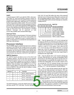
The table below shows the divider values for some of the most
commonly used LTC frame rates.
LXCLKSEL — This bit controls the source for the LTC
transmit clock divider input. A 0 selects the internal 14.318
MHz clock and a 1 selects the LTC receive clock. When the
LTC receive clock is selected as the source to the LTC transmit
clock divider, the clock rate is first doubled before being
input to the divider so that loading a divider value of 001 will
result in the LTC transmit clock running at the exact same rate
as the LTCreceive clock.
LTC FRAME RATE
30 Hz
DIVIDER VALUE
BA6h
BA9h
DFBh
E90h
29.97 Hz
25 Hz
24 Hz
LTXEN — This bit, when set to 1, enables output of LTC
code on the LTCOUT output pin. LTXEN is synchronized
with the selected LTC SYNC source to ensure that only
7
6
5
4
3
2
1
0
LTC BitTime (write only)
IR36 – (low byte)
IR37 – (high byte)
ICS2008B
9

 IDT [ INTEGRATED DEVICE TECHNOLOGY ]