ICS1493-19
CLOCK GENERATOR FOR AUTOMOTIVE APPLICATION
Parameter
Symbol
Conditions
Min.
Typ. Max. Units
Jitter, Peak-to-peak
Peak-to-peak, reference clock
19.35 MHz
250
ps
ppm
ms
Output Frequency
Synthesis Error
All clocks
10
Transition Time
t
Measured from a change of FSEL
until clock stable within 1%
1
TR
Thermal Characteristics
Parameter
Symbol
Conditions
Min.
Typ. Max. Units
Thermal Resistance Junction to
Ambient
θ
Still air
83
75
61
60
° C/W
° C/W
° C/W
° C/W
JA
θ
1 m/s air flow
3 m/s air flow
JA
θ
JA
Thermal Resistance Junction to Case
θ
JC
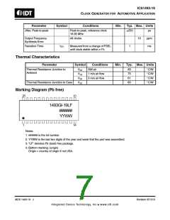
Marking Diagram (Pb free)
28
15
1493GI-19LF
######
YYWW
14
1
Notes:
1. ###### is the lot number.
2. YYWW is the last two digits of the year and week that the part was assembled.
3. “LF” denotes Pb (lead) free package.
4. Bottom marking: (origin)
Origin = country of origin if not USA.
MDS 1493-19 J
7
Revision 051310
Integrated Device Technology, Inc.● www.idt.com

 IDT [ INTEGRATED DEVICE TECHNOLOGY ]