ICS1531 Data Sheet - Preliminary
Chapter 3 Pin Diagram and Listings
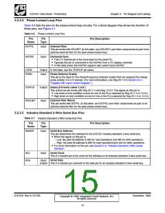
3.2.3.4 Phase-Locked Loop Pins
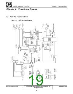
Table 3-6 lists the pins for the phase-locked loop circuitry. For a block diagram that shows the function of
these pins, see Figure 4-1.
Table 3-6. Phase-Locked Loop Pins
Pin
Pin
Pin Description
Name
Type
EXTFIL
Input
External Filter.
This pin works with XFILRET (in this table, see XFILRET) and other components as part of an
optional external filter for the pixel phase-locked loop.
H•orTizhoisn5ta-Vl Styolnecra. nt pin is the clock input for the pixel PLL.
HSYNC
Input
• Typically this pin is connected to the HSYNC from a PC display controller.
• In this data sheet, this HSYNC signal is also called ‘input HSYNC’.
LOCK
PDEN
Output In this table, see the ‘STATUS’ pin name.
Input
Phase-Detector Enable.
This pin is the input for the Phase/Frequency Detector enable that can suspend the charge
pump activity. It is 5-V tolerant. (For more information, see Reg 00:1-0 in Section 6.5.1,
“Register 00h: Input Control Register”.)
STATUS
XFILRET
Output Status (Formerly called ‘Lock’).
T•hisLoawctiwveh-elonwaploinckwcoorknsdiwtioithn Rocecgu2rsCf:o1r-0onaendofRtheeg P12L:L3s-2s.eTlehcetesdigbnyalRoength2iCs:p1i-n0iosr: 12:3-2.
• High when no lock condition occurs for one of the PLLs selected by Reg 2C:1-0 or 12:3-2.
Input
External Filter Return.
This pin works with EXTFIL (in this table, see EXTFIL) and other components as part of an
optional external filter for the pixel phase-locked loop.
3.2.3.5 Industry-Standard 2-Wire Serial Bus Pins
Table 3-7. Industry-Standard 2-Wire Serial Bus Pins
Pin
Pin
Pin Description
Name
Type
SBADR
Input
Serial Bus Address.
T•hisWphinendethteermsiginneasl tohnetahdisdpreinssisf:or the ICS1531 industry-standard 2-wire serial bus.
– Low, the pixel bit address is 49h for read operations and 48h for write operations.
– High, the pixel bit address is 4Bh for read operations and 4Ah for write operations.
• For more information on this pin, see Section 2.9, “Industry-Standard 2-Wire Serial
Interface”.
SCL
SDA
Input
Serial Clock.
This 5-V tolerant pin is the clock for the interface to an industry-standard 2-wire serial bus.
Input/
Serial Data.
Output This 5-V tolerant pin connects to the data pin for an industry-standard 2-wire serial bus.
ICS1531 Rev N 12/1/99
December, 1999
Copyright © 1999, Integrated Circuit Systems, Inc.
All rights reserved.
15

 ICSI [ INTEGRATED CIRCUIT SOLUTION INC ]