ICS1531 Data Sheet - Preliminary
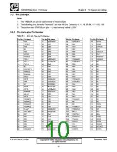
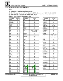
Chapter 3 Pin Diagram and Listings
3.2.3.3 Pixel Data Pins
Table 3-5. Pixel Data Pins
Pin
Pin
Pin Description
Name
Type
A•naTlohegsBelpuien,sAancacleopgt aGnraeleong,dAantaalfoorgtRheedA.DC blue, green, and red channels.
• Typically, the data for these pins comes from a PC display controller.
ABLUE,
AGRN,
ARED
Input
B•luTeh(e‘Asechpiannsnoeul’t)puAt7fi–rsAt b0l,uGe,regerene(n‘,Aacnhdarnendepli’x)eAl7da–taA,0r,eRspeedct(i‘vAelcyh. annel’) A7 – A0.
• A7 pins reflect most-significant data bits. A0 pins reflect least-significant data bits.
BA7 – BA0,
GA7 – GA0,
RA7 – RA0
Output
Output
B•luTeh(e‘Bsechpiannsnoeult’)puBt7s–ecBo0n,dGbrlueee,ng(r‘eBecnh, aanndnerel’d) Bpi7xe–l Bda0t,aR, eredsp(‘eBctcivhealny.nel’) B7 – B0.
BB7 – BB0,
GB7 – GB0,
RB7 – RB0
• B7 pins reflect most-significant data bits. B0 pins reflect least-significant data bits.
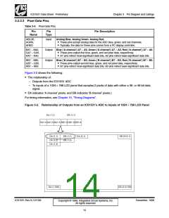
Figure 3-2 shows the following:
• The relationship of:
– Outputs from the ICS1531 ADC
– To inputs of a 1024 × 768 LCD panel that samples 2 pixels of data with either a 36- or 48-bit data
signal.
• DA indicates ‘A channel’ pixels, and DB indicates ‘B channel’ pixels.)
For timing information, see Chapter 10, “Timing Diagrams”.
Figure 3-2. Relationship of Outputs from an ICS1531’s ADC to Inputs of 1024 × 768 LCD Panel
DA (1,1)
DB (1,1)
RA7-0 GA7-0 BA7-0 RB7-0 GB7-0 BB7-0
DA (1,1)
DA (1,2)
DA (1,3)
DB (1,1)
DB (1,2)
DA (2,1)
DB (512,1)
DA (1,768)
DB (512,768)
ICS1531 Rev N 12/1/99
December, 1999
Copyright © 1999, Integrated Circuit Systems, Inc.
All rights reserved.
14

 ICSI [ INTEGRATED CIRCUIT SOLUTION INC ]