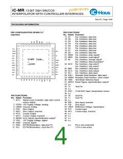
iC-MR 13-BIT S&H SIN/COS
INTERPOLATOR WITH CONTROLLER INTERFACES
Rev A1, Page 8/44
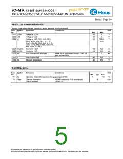
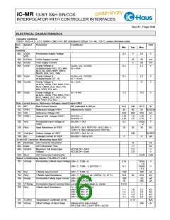
ELECTRICAL CHARACTERISTICS
Operating conditions:
VDDA = VDD = 4.5...5.5 V, GNDA = GND = 0 V, IBP calibrated to 200 µA, Tj = -40...125 °C, unless otherwise noted.
Item Symbol
No.
Parameter
Conditions
Unit
Min.
Typ.
Max.
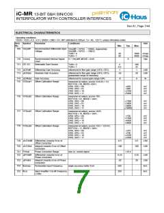
Amplitude Control, Output ACO
801
Vs()hi
Saturation Voltage hi
Vs()hi = VDD − V();
ACOR = 00, I() = -5 mA
ACOR = 01, I() = -10 mA
ACOR = 10, I() = -25 mA
ACOR = 11, I() = -50 mA
1
1
1
1
V
V
V
V
802
Isc()hi
Short-Circuit Current hi in ACO
V() = 0 V ... VDD − 1 V;
ACOR = 00
-10
-20
-50
-5
mA
mA
mA
mA
ACOR = 01
ACOR = 10
ACOR = 11
-10
-25
-50
-100
803 tr()
Rise Time Current Source ACO I(ACO): 0 % → 90 % of setpoint
1
ms
µs
804
tset()
Settling Time Current Source
ACO
square control active,
400
I(ACO): 50 % → 100 % of setpoint
Vscq() = Vpp(V(PSO) - V(NSO)), respectively
Vscq() = Vpp(V(PCO) - V(NCO));
ACOC = 0x19
805
Vscq()
Regulated Mean Target
Amplitude with Square Control
500
mV
806
Vdc()
Regulated Mean Setpoint with
Sum Control
ACOD = 0x00
ACOD = 0x7F
166
551
mV
mV
807 It()min
808 It()max
809 Vt()min
810 Vt()max
Signal Filter
Monitoring of ACO Output Cur-
rent, lower threshold
referenced to current range ACOR
referenced to current range ACOR
referenced to Vscq()
3
%Isc
%Isc
%
Monitoring of ACO Output Cur-
rent, upper threshold
90
Monitoring of Signal Level 1,
lower threshold
40
Monitoring of Signal Level 2,
upper threshold
referenced to Vscq()
135
%
901
fc()
Cut-off Frequency
Phase Shift
ENF = 1, SELBP = 0; fin < 10 Hz
fin > 100 kHz
15
2400
kHz
kHz
902
PHI()
ENF = 1, SELBP = 0,
1.5
°
fin = 100 kHz for sine and cosine
Analog Outputs PSO, NSO, PCO and NCO
A01
Vpk()max Permissible Maximum Output
Amplitude
VDDA = 4.5 V, DC level VDDA/2,
RL = 50 Ω vs. VDDA/2
300
275
mV
mV
A02 Vpk()
Output Amplitude with Sensor
Tracking by Output ACO
ACOC = 0x19
CL = 250 pF
225
500
250
A03 fc
Cut-off Frequency
kHz
µV
A04 Vos
Output Offset Voltage
Short-Circuit Current hi
Short-Circuit Current lo
Slew Rate
±200
-20
20
A05 Isc()hi
A06 Isc()lo
A07 SR()
A08 Rout()
A09 fout()cal
V() = 0 V
-40
15
-15
40
mA
mA
V/µs
kΩ
V() = VDD
RLdiff = 100 Ω, CL = 25 pF
MODE = 0x01 (Analog 1)
MODE = 0x01 (Analog 1), CL = 200 pF
5
Test Signal Source Resistance
5
Permissible Test Signal Output
Frequency
2
kHz
Signal Level Monitoring
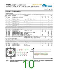
B01 Vpp()max Signal Level Monitoring,
upper threshold
referenced to target amplitude of converter and
analog output, see Figure 1
110
10
150
50
%Vpp
%Vpp
mV
B02 Vpp()min Signal Level Monitoring,
lower threshold
referenced to target amplitude of converter and
analog output, see Figure 1
B03 Vpp()hys Signal Level Monitoring,
Hysteresis
referenced to Vpp()min, Vpp()max
referenced to VPAH, see Figure 2
referenced to VPAH, see Figure 2
30
140
70
B04 Vdc()max Mean Value Monitoring,
upper threshold
120
50
%VPAH
%VPAH
B05 Vdc()min Mean Value Monitoring,
lower threshold

 ICHAUS [ IC-HAUS GMBH ]