iC-MR 13-BIT S&H SIN/COS
INTERPOLATOR WITH CONTROLLER INTERFACES
Rev A1, Page 11/44
OPERATING CONDITIONS: PARALLEL I/O INTERFACE
Operating conditions: VDDA = VDD = 4.5...5.5 V, GNDA = GND = 0 V, IBP calibrated to 200 µA, Tj = -40...125 °C
Item Symbol
No.
Parameter
Conditions
Unit
Min.
Max.
I001 tsAW
I002 thWA
I003 tsDW
I004 thWD
I005 tWL
I006 tRL
Setup Time:
addresses stable before NWR hi → lo
Hold Time:
addresses stable after NWR lo → hi
Setup Time:
data stable before NWR hi → lo
Hold Time:
data stable after NWR lo → hi
Signal Duration:
NWR at low level
50
50
50
50
80
80
50
80
80
80
ns
ns
ns
ns
ns
ns
ns
ns
ns
ns
Signal Duration:
NRD at low level
I007 tpRD1
I008 tpRD2
I009 tWW
I010 tWR
Propagation Delay:
data stable after NRD hi → lo
Propagation Delay:
data bus high ohmic after NRD lo → hi
Signal Duration:
between NWR lo → hi and hi → lo
Signal Duration:
CL = 10 pF
between NWR lo → hi and NRD hi → lo
or NRD lo → hi and NWR hi → lo
I011 tRR
I012 tCL
Signal Duration:
80
80
ns
ns
between NRD lo → hi and hi → lo
Signal Duration:
between NCS hi → lo and NRD hi → lo
or NCS hi → lo und NWR hi → lo
Signal Duration:
I013 tCH
80
ns
between NRD lo → hi and NCS lo → hi
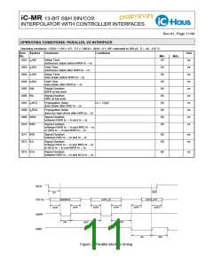
NCS
tCH
tCL
ADDRESS
DATA_IN
DATA_OUT
D(7:0)
NWR
NRD
t AW
h
t DW
s
t DW
h
t RD1
p
t RD2
p
t AW
s
tWL
tWW
tWR
tRL
tRR
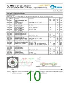
Figure 3: Parallel interface timing.

 ICHAUS [ IC-HAUS GMBH ]