iC-JX
16-FOLD 24 V HIGH-SIDE DRIVER WITH µC INTERFACE
Rev C1, Page 2/36
DESCRIPTION
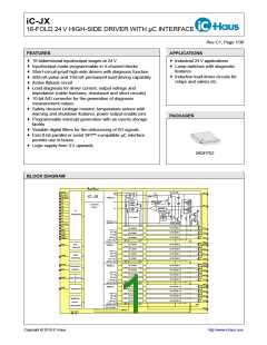
iC-JX is a bidirectional I/O device with 4x4 high-side and generates interrupt messages for the controller.
driver stages. The input or output function can be The latter is warned before the device is forcibly shut-
separately selected for blocks or nibbles of four I/O down. A short circuit also triggers an interrupt mes-
stages.
sage; the current status here can be read out by the
controller.
Each block can also be individually programmed with
various filtering options for the debouncing of I/O For the purpose of load diagnosis a programmable
pin signals or overcurrent messages, with current pull-up current source (of up to 2 mA) can be used
sources for the defining of levels at the inputs (low- to determine an initial load breakage or open loop
side sources) or for load diagnosis at the outputs (caused by a fractured cable, for example) before
(high-side sources) and also with a flash pulse func- an output is switched on. The I/O pin status can
tion.
always be read back via comparators. A load cur-
rent measurement circuit then permits the load to be
To enable communication with the controller the de- assessed; failed valves and faulty or wrongly imple-
vice includes a parallel interface (with eight data, five mented indicator lamps can be verified in this way. In
address and three control pins) and also an SPI- addition, the analog measurement of voltage at the
compatible serial interface (with one pin for the clock, I/O pins allows safety switches to be analyzed with
chip selection, data input and data output respec- reference to ground, here without the driver function.
tively). The type of interface is selected via pin NSP.
All analog measurements for the load current (per
I/O stages with an input function can record logic stage), for the I/O pin voltage (per stage, either refer-
levels at 24 V where a programmable pull-down cur- enced to Ground or VB), for the driver supply (all VB
rent source (of up to 2 mA) either defines the level pins) , for the internal voltage reference (VBG) and
for open inputs or supplies a bias current for exter- for the chip temperature are made available to the
nal switch contacts. Connecting safety circuits with microcontroller as digital measurements by an inte-
integrated serial/parallel resistors to the device also grated A/D converter which has 10 bits of resolution.
enables leakage currents and short circuits to be pin-
pointed. The contact status can be read out using the An interrupt pipeline which limits the loss of interrupts
microcontroller interface.
allows reliable processing of interrupts by the micro-
controller. Registers provide information as to current
I/O stages with an output function drive various loads events; messages can be individually enabled for all
(such as lamps, cables or relays, for example) to a available interrupt sources.
common ground with 150 mA of permanent current
or 500 mA in pulse operation. Spikes and flyback iC-JX monitors all supply voltages and also the
currents are discharged by the integrated flyback cir- GNDD-GNDA connection to ground.
cuits.
Monitored separately, undervoltage in the range of
For synchronous flash display, as used for indicator 2.5V at analog supply VCC or even short disruption
lamps in plugboards, for example, a flash pulse en- of digital supply VDD causes all registers to be reset
able can be individually set for each output to offload and the output stages to be shutdown.
the controller. A common inhibiting input (POE) per- Undervoltage at 24 V driver supply VB triggers a
mits the global shutdown of all outputs and can be shutdown of the output stages without deleting the
operated by an autonomous watchdog circuit.
contents of the registers.
All output stages are short-circuit-proof and pro- Diodes protect all inputs and outputs against destruc-
tected against thermal destruction in the event of ex- tion by ESD. iC-JX is also immune to burst transients
treme power dissipation. Each stage has its own according to IEC 1000-4-4 (4 kV; previously IEC 801-
temperature sensor which is evaluated in two stages 4).

 ICHAUS [ IC-HAUS GMBH ]