IBM3009K2672
IBM SONET/SDH Framer
field is set to indicate no defect detected within 100 ms from when the SONET/SDH framer detects termina-
tion of the defect. The mating SONET/SDH framer will insert these path RDI and FEBE values into its trans-
mit G1 byte stream for the appropriate VC-4 or VC-4c. Again, while RING is set to ‘1’, path FEBE and RDI are
not locally transmitted but are instead communicated to a mating SONET/SDH framer which will insert them
into its transmit SONET/SDH stream.
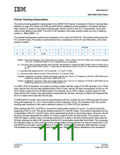
All of the data fields depicted in the previous figures are output by the SONET/SDH framer even if there are
no errors or actions to report.
Finally, when RING is set to ’0’, nothing is sent out on the transmit ring port but the transmit ring port clock
remains active.
When the RING bit is set to ‘1’, the SONET/SDH framer processes the K1-K3, G1 and Line RDI/REI and their
associated indication bits via the ring port as indicated below. Keep in mind that no POH processing (particu-
larly G1 and K3) is performed by the SONET/SDH framer when the Telecom Bus mode of operation is
selected, regardless of the setting of the RING bit. Therefore, for the cases below where K3 and G1 process-
ing are mentioned, Telecom Bus mode is assumed to be turned off.
• 4 x STM-1/STS-3c mode
- K1 - K3, their associated indication bits, G1, and Line RDI/REI are processed for each individual
STM-1/STS-3c.
• STM-4/STS-12 mode
- K1, K2 plus the New APS indication bit, and Line RDI, are processed only for the first STM-1/STS-3c.
- Line REI is processed only for the third STM-1/STS-3c. The receive B2 errors from the twelve B2
bytes received from the line are summed by macro 3 and transferred to a mating SONET/SDH framer
which then outputs this value to its line via the transmit M1 byte. The M1 byte is located in row 9 col-
umn 15 (the third A2 byte is also in column 15) of the STM-4/STS-12 frame.
- K3 is processed for all 4 VC-4.
- G1 is processed for all 4 VC-4.
• STM-4c/STS-12c mode
- K1, K2 plus the New APS indication bit, and Line RDI, are processed only for the first STM-1/STS-3c.
- Line REI is processed only for the third STM-1/STS-3c. The receive B2 errors from the twelve B2
bytes received from the line are summed by macro 3 and transferred to a mating SONET/SDH framer
which then outputs this value to its line output via the transmit M1 byte. The M1 byte is located in row
9 column 15 (the third A2 byte is also in column 15) of the STM-4c/STS-12c frame.
- There is only one K3 byte that is processed since there is only one column of POH.
- There is only one G1 byte that is processed since there is only one column of POH.
• STM-16/STM-4c or STS-48/STS-12c mode
- K1, K2 plus the New APS indication bit, and Line RDI, are processed only for the first STM-1/STS-3c
in the SONET/SDH framer that corresponds to STM-4c/STS-12c 1.
- Line REI is processed only for the third STM-1/STS-3c in the SONET/SDH framer that corresponds
to STM-4c/STS-12c 1. The receive B2 errors from the twelve B2 bytes received from the line and the
expansion port are summed by macro 3 of the SONET/SDH framer that corresponds to STM-
4c/STS-12c 1 and are transferred to a mating SONET/SDH framer which then outputs this value to its
line output via the transmit M1 byte. The M1 byte is located in row 9 column 51 (the third A2 byte is
also in column 51) of the STM-16/STS-48 frame.
- Only one K3 byte is processed in each SONET/SDH framer as there is only one K3 byte in a VC-4c.
- Only one G1 byte is processed in each SONET/SDH framer as there is only one G1 byte in a VC-4c.
ssframer.01
8/27/99
Operation
Page 99 of 279

 IBM [ IBM ]