Charge Pump Voltage Converters
TJ7660
TJ7660
TJ7660
Typical Applications
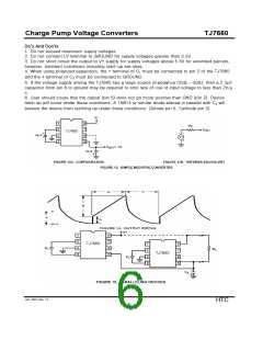
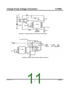
Simple Negative Voltage Converter
Themajority of applications will undoubtedly utilize the TJ7660 for generation of negative supply
voltages. Figure 13 shows typical connections to provide a negative supply negative (GND) for
supply voltages below 3.5V.
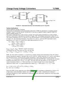
The output characteristics of the circuit in Figure 13A can be approximated by an ideal voltage
source in series with a resistance as shown in Figure 13B. The voltage source has a value of -V+.
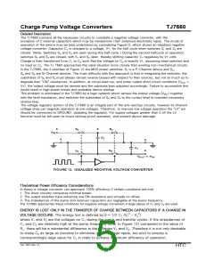
The output impedance (RO) is a function of the ON resistance of the internal MOS switches (shown
in Figure 12), the switching frequency, the value of C1 and C2, and the ESR (equivalent series
resistance) of C1 and C2. A good first order approximation for RO is:
RO = 2(RSW1 + RSW3 + ESRC1) +
2(RSW2 + RSW4 + ESRC1) +
RO = 2(RSW1 + RSW3 + ESRC1) +
1/(fPUMP) (C1)+ ESRC2
(fPUMP = fOSC/2 , RSWX = MOSFET switch resistance)
Combining the four RSWX terms as RSW, we see that:
RO = 2 (RSW) + 1/(fPUMP) (C1)+ 4 (ESRC1) + ESRC2
RSW, the total switch resistance, is a function of supply voltage and temperature (See the Output
Source Resistance graphs), typically 23Ω at 25oC and 5V. Careful selection of C1 and C2 will reduce
the remaining terms, minimizing the output impedance. High value capacitors will reduce the
1/(fPUMP • C1) component, and low ESR capacitors will lower the ESR term. Increasing the oscillator
frequency will reduce the 1/(fPUMP • C1) term, but may have the side effect of a net increase in
output impedance when C1 > 10µF and there is no longer enough time to fully charge the
capacitors every cycle. In a typical application where fOSC = 10kHz and C = C1 = C2 = 10µF:
RO = 2 (23) +1/(5 • 103) (10-5)+ 4 (ESRC1) + ESRC2
RO = 46 + 20 + 5 (ESRC)
Since the ESRs of the capacitors are reflected in the output impedance multiplied by a factor of 5,
a high value could potentially swamp out a low 1/(fPUMP • C1) term, rendering an increase in
switching frequency or filter capacitance ineffective. Typical electrolytic capacitors may have ESRs
as high as 10Ω.
Jan. 2007-Rev 1.0
HTC
7

 HTC [ HTC KOREA TAEJIN TECHNOLOGY CO. ]