HI-6110 (BUS CONTROLLER MODE)
BUS CONTROLLER
INITIALIZATION
The HI-6110 is configured for Bus Controller operation by setting
the BCMODE input high and the RTMODE input low.
Alternatively, Control Register bits 3:2 (RTMODE:BCMODE) may
be programmed to 0:1. Control Register bits 3:2 are logically
ORed with the input pins with the same signal name.
In Bus Controller mode, the user must first perform a Master
Reset to initialize the BC protocol engine and clear all message
registers and data FIFOs. This may be achieved by pulsing the
MR input high, or writing a "1" to Control Register bit 0. The user
must select a master clock (CLK) frequency by programming
Control Register bits 11 and 12, and the Response Time Out must
be programmed per Control Register bit 14. Refer to the BC
Register Formats section for a full description of available
registers and their functions in Bus Controller Mode.
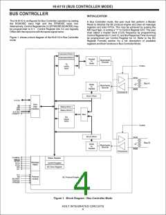
Figure 1. shows a block diagram of the HI-6110 in Bus Controller
mode
Command Word 1
Command Word 2
Parallel
Manchester
to
Encoder
Serial
TX
DATA
FIFO
TXINHA
BUSA
Bus A
Serial
Manchester
to
Decoder
Parallel
BUSA
Transceiver
Bus A Word
D15-D0
Host
Data
Interface
CS
R/W
STR
Status Word 1
Status Word 2
RA2-RA0
FFEMPTY
Mux
RX
DATA
FIFO
TXINHB
Bus B Word
BUSB
Bus B
Serial
Manchester
to
Decoder
Parallel
BUSB
Transceiver
VALMESS
ERROR
RFLAG
RCVA
Status Register
Message
Status
Control Register
BC Error Register
RCVB
RF0
RF1
CLK
MR
BCSTART
BCMODE
RTMODE
Protocol
Control
BC Protocol Engine
Figure 1. Block Diagram - Bus Controller Mode
HOLT INTEGRATED CIRCUITS
4

 HOLTIC [ HOLT INTEGRATED CIRCUITS ]