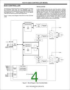
HI-6110 (BUS CONTROLLER MODE)
ISSUING BC COMMANDS
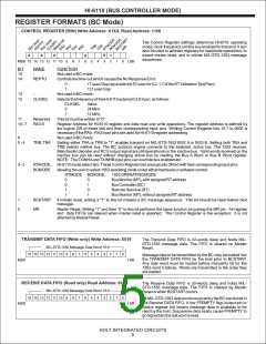
Register operations in the HI-6110 can be addressed using either
the RA0-RA3 inputs or the RA3:RA0 bits in the Control Register.
Each RA input is logically ORed with its corresponding Control
Register bit. When using input pins for register addressing, the
Control Register bits 10:7 must be reset. Register addressing via
Control Register bits 10:7 is a 2-step process. First, the target
register address is written to the Control Register (and the RA0-
RA3 inputs must be held low). Next, the desired register operation
is performed: the Control Register provides the register address
while the R/W and STB inputs specify data direction and clock the
data transfer.
There are limited circumstances when VALMESS may be
followed by ERROR. For example, if the BC requests an RT
response with 4 data words but instead receives 5, the extra data
word will cause the VALMESS flag to be reset and ERROR to be
set. The host controller has the option of reading RT responses
on-the-fly by monitoring the RFLAG and FFEMPTY flags, or may
simply wait for end of sequence flags, VALMESS or ERROR.
While the Transmit Data FIFO may be pre-loaded before starting
a message sequence, any data word may be loaded on the fly, as
long as it is written before mid-sync during that word’s transmit
window. In order to have the full 32 word capacity available, the
Transmit Data FIFO should be cleared before writing data. The
FIFO is cleared at Master Reset, or when VALMESS or ERROR is
asserted at the end of a message.
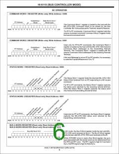
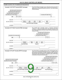
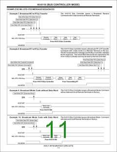
A MIL-STD-1553 Bus Controller message can be pre-loaded into
the HI-6110 by writing the required Command Word to the
Command Word 1 Register. The Command Word 2 register is
used to hold the second (Transmit) Command Word for RT to RT
commands. Message data for MIL-STD-1553 Receive
commands are loaded by the host into the Transmit Data FIFO.
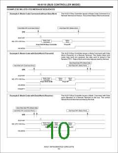
For Mode Code commands with data word, a data word to be
transmitted must be written to theTransmit Data FIFO.
The Receive Data FIFO is cleared at Master Reset, or by
performing a series of FIFO read operations until FFEMPTY goes
high. The Receive Data FIFO will not accept new receive data
when full. The FIFO must have at least one empty register by mid-
sync within the time window for any incoming data word.
A BC message sequence commences when a positive edge
occurs at the BCSTART input pin, or when Control Register bit 1
(BCSTART) transitions from 0 to 1 as a result of a register write
operation by the Host. Control Register bit 1 is NOT automatically
reset upon BC message sequence execution. Therefore, when
using the Control Register to start message sequences, it is first
necessary to reset bit 1 before it is set to initiate the next message
sequence. The MIL-STD-1553 message is properly formatted by
the HI-6110 and output on the selected MIL-STD-1553 data bus.
The HI-6110 waits for a response from the MIL-STD-1553 bus if
the command type expects a response. The responding RT's
Status Word is captured in the HI-6110 Status Word 1 Register.
The Status Word 2 register is used to capture the Status Word
from the transmitting RT during RT-to-RT transfer commands.
Message data words received from the transmitting RT are stored
in the Receive Data FIFO. A mode data word received from the
transmitting RTis also stored in the Receive Data FIFO.
If the reply from the MIL-STD-1553 responding terminal was a
valid response and met all response time, Sync and Data
encoding, parity checks, word count, RT address, and contiguous
message requirements, then the VALMESS output pin goes high
and bit 7 in the Status Register is set. The host may then retrieve
the contents of the Status Word register(s) and Receive Data
FIFO as required by the application software. The FFEMPTY
output pin will be low if the FIFO contains at least one data word,
and the corresponding bit 3 in the Status Register will be set.
When all data words have been read by the host controller, the
FFEMPTY output pin goes high, and bit 3 in the Status Register is
reset.
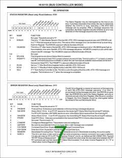
The final result of any BC message sequence is assertion of
either a VALMESS flag or an ERROR flag. If an error is detected
during a MIL-STD-1553 message sequence, the ERROR output
pin is asserted, corresponding bit 8 in the Status Register is set,
and the appropriate error bit(s) are set in the Error Register. The
host may interrogate the Error Register to determine what action
is necessary to correct the error. The VALMESS output remains
low for any message for which an error is detected.
HOLT INTEGRATED CIRCUITS
8

 HOLTIC [ HOLT INTEGRATED CIRCUITS ]