HI-6110
FUNCTIONAL DESCRIPTION
HOST INTERFACE
The HI-6110 is further configured by setting various configuration
bits in the on-chip Control Register. Different sets of 16-bit
registers and message data FIFOs are available depending upon
the mode of operation (BC, RT or MT). The STR pin is used as the
timing signal for data read and write cycles. Data is output on the
16-bit bidirectional data bus, D15-D0, when R/W is high and STR
is low. D15-D0 are inputs when R/W is low, and data is written into
internal registers on the rising edge of the STR signal. The Chip
Select input CS must be low for all register read / write operations:
The Holt HI-6110 provides a simple interface between a host
subsystem and a MIL-STD-1553 dual redundant data bus.
Messages are processed one at
a time. The HI-6110
automatically handles message formatting, error checking,
message data buffering, protocol checking and default
responses. The host may override default message responses by
updating registers on-the-fly.
The host communicates with the HI-6110 using a 16-bit
bidirectional data bus. On-chip bus transceivers allow the device
to be connected to the MIL-STD-1553 data buses using external
coupling transformers.
CS R/W STR D15-D0
OPERATION
1
0
0
0
X
X
1
0
X
1
0
0
High impedance No operation
High impedance No operation
Output
Input
Read
Write (on STR rising edge)
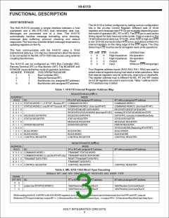
The HI-6110 can be configured as 1553 Bus Controller (BC),
Remote Terminal (RT) or Bus Monitor (MT). The BCMODE and
RTMODE inputs define the mode of operation as follows:
BCMODE RTMODE 1553 OPERATING MODE
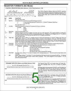
Four Register address inputs (RA3, RA2, RA1, RA0) are used to
select internal registers during host read or write operations. Note
that internal registers may be write-only, read-only or read/write.
The register address map is different for BC, RT and MT modes
as not all registers are used in each mode. Table 1 defines the HI-
6110 address map in detail.
1
0
1
0
0
1
1
0
Bus Controller (BC)
RemoteTerminal (RT)
Bus Monitor (no assigned RTaddress)
Bus Monitor with assigned RTaddress
Table 1. HI-6110 Internal Register Address Map
REGISTER READ (R/W=1)
MODE
ADDRESS
RA3:0
BC
RTor MTwith assigned RTaddress
MTwithout assigned RTaddress
COMMAND WORD 1
0 0 0 0 STATUS WORD 1 ( if RT-RT, Receive RT) COMMAND WORD 1
0 0 0 1 STATUS WORD 2 only RT-RTTransmit RT COMMAND WORD 2 (from last RT-RT)
COMMAND WORD 2 (from last RT-RT)
RECEIVED MODE DATAWORD
0 0 1 0
0 0 1 1
-
-
RECEIVED MODE DATAWORD
RECEIVED STATUS WORD (from last RT-RT) Xmitting RTSTATUS WORD for RTRT
0 1 0 0 RECEIVED DATAFIFO
0 1 0 1 STATUS REGISTER
RECEIVED DATAFIFO
STATUS REGISTER
MESSAGE REGISTER
ERROR REGISTER
-
DATAFIFO, includes Xmitted Mode Data
STATUS REGISTER
0 1 1 0
0 1 1 1 ERROR REGISTER
1 0 0 0
-
MESSAGE REGISTER
ERROR REGISTER
-
STATUS WORD (Receiving RTif RTRT)
BUSAWORD
1 0 0 1 BUSAWORD
BUSAWORD
1 0 1 0 BUS B WORD
BUS B WORD
BUS B WORD
1 1 0 0 CONTROLREGISTER
CONTROLREGISTER
CONTROLREGISTER
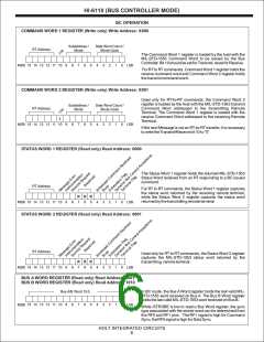
REGISTER WRITE (R/W=0)
MODE
ADDRESS
RA3:0
BC
RTor MTwith assigned RTaddress
TRANSMITSTATUS WORD
MTwithout assigned RTaddress
X 0 0 0 COMMAND WORD 1
X 0 0 1 COMMAND WORD 2 ( used for RT-RTonly) TRANSMITMODE DATAWORD
-
X 0 1 0 TRANSMITDATA FIFO
X 0 1 1
RESETTRANSMITDATAFIFO
TRANSMITDATAFIFO
-
-
-
X 1 X X CONTROLREGISTER
CONTROLREGISTER
CONTROLREGISTER
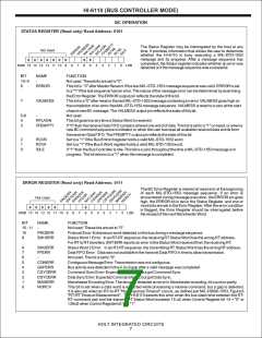
Table 2. MIL-STD-1553 Word Type Decoding
SIGNALS RF1 AND RF0 IDENTIFY LAST RECEIVED 1553 WORD TYPE
MODE
SIGNAL
RF1 RF0 BC
RTor MTwith assigned RTaddress
-
MTwithout assigned RTaddress
0
0
1
0
1
0
-
-
pulses low if STATUS WORD 2
-
Valid Receive Command BusA
Valid Receive Command Bus B
Valid Receive Command BusA
Valid Receive Command Bus B
While reading the BUS AWORD or BUS B WORD registers, sync type for the stored word can be determined from the RF0 and RF1 outputs.
While the /STR input is held low, output RF1 = 1 if the stored Bus Word had Command Sync, or output RF0 = 1 if the stored Bus Word had Data Sync.
HOLT INTEGRATED CIRCUITS
3

 HOLTIC [ HOLT INTEGRATED CIRCUITS ]