HT46RU66/HT46CU66
¨
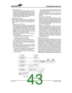
Transmitting data
Start
Bit
Data
Bits
Address Parity
Stop
Bit
When the UART is transmitting data, the data is
shifted on the TX pin from the shift register, with the
least significant bit first. In the transmit mode, the
TXR register forms a buffer between the internal
bus and the transmitter shift register. It should be
noted that if 9-bit data format has been selected,
then the MSB will be taken from the TX8 bit in the
UCR1 register. The steps to initiate a data transfer
can be summarized as follows:
Bits
Bits
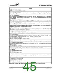
Example of 8-bit Data Formats
1
1
1
8
7
7
0
0
0
1
0
1
1
1
11
Example of 9-bit Data Formats
1
1
1
9
8
8
0
0
0
1
0
1
1
1
-
Make the correct selection of the BNO, PRT,
PREN and STOPS bits to define the required
word length, parity type and number of stop bits.
11
-
Setup the BRG register to select the desired baud
rate.
Transmitter Receiver Data Format
-
Set the TXEN bit to ensure that the TX pin is used
The following diagram shows the transmit and receive
waveforms for both 8-bit and 9-bit data formats.
as a UART transmitter pin and not as an I/O pin.
-
Access the USR register and write the data that is
·
UART transmitter
to be transmitted into the TXR register. Note that
this step will clear the TXIF bit.
Data word lengths of either 8 or 9 bits, can be selected
by programming the BNO bit in the UCR1 register.
When BNO bit is set, the word length will be set to 9
bits. In this case the 9th bit, which is the MSB, needs
to be stored in the TX8 bit in the UCR1 register. At the
transmitter core lies the Transmitter Shift Register,
more commonly known as the TSR, whose data is ob-
tained from the transmit data register, which is known
as the TXR register. The data to be transmitted is
loaded into this TXR register by the application pro-
gram. The TSR register is not written to with new data
until the stop bit from the previous transmission has
been sent out. As soon as this stop bit has been trans-
mitted, the TSR can then be loaded with new data
from the TXR register, if it is available. It should be
noted that the TSR register, unlike many other regis-
ters, is not directly mapped into the Data Memory area
and as such is not available to the application program
for direct read/write operations. An actual transmis-
sion of data will normally be enabled when the TXEN
bit is set, but the data will not be transmitted until the
TXR register has been loaded with data and the baud
rate generator has defined a shift clock source. How-
ever, the transmission can also be initiated by first
loading data into the TXR register, after which the
TXEN bit can be set. When a transmission of data be-
gins, the TSR is normally empty, in which case a
transfer to the TXR register will result in an immediate
transfer to the TSR. If during a transmission the TXEN
bit is cleared, the transmission will immediately cease
and the transmitter will be reset. The TX output pin will
then return to having a normal general purpose I/O pin
function.
-
This sequence of events can now be repeated to
send additional data.
It should be noted that when TXIF=0, data will be in-
hibited from being written to the TXR register. Clear-
ing the TXIF flag is always achieved using the
following software sequence:
1. A USR register access
2. A TXR register write execution
The read-only TXIF flag is set by the UART hard-
ware and if set indicates that the TXR register is
empty and that other data can now be written into
the TXR register without overwriting the previous
data. If the TEIE bit is set then the TXIF flag will gen-
erate an interrupt.
During a data transmission, a write instruction to the
TXR register will place the data into the TXR regis-
ter, which will be copied to the shift register at the
end of the present transmission. When there is no
data transmission in progress, a write instruction to
the TXR register will place the data directly into the
shift register, resulting in the commencement of
data transmission, and the TXIF bit being immedi-
ately set. When a frame transmission is complete,
which happens after stop bits are sent or after the
break frame, the TIDLE bit will be set. To clear the
TIDLE bit the following software sequence is used:
1. A USR register access
2. A TXR register write execution
Note that both the TXIF and TIDLE bits are cleared
by the same software sequence.
N
e
x
t
P
a
r
i
t
y
B
i
t
S
t
a
r
t
S
t
a
r
t
B
i
t
B
i
t
0
B
i
t
1
B
i
t
2
B
i
t
3
B
i
t
4
B
i
t
5
B
i
t
6
B
i
t
7
B
i
t
S
t
o
p
B
i
t
8
-
B
i
t
D
a
t
a
F
o
r
m
a
t
N
e
x
t
P
a
r
i
t
y
B
i
t
S
t
a
r
t
S
t
a
r
t
B
i
t
B
i
t
0
B
i
t
1
B
i
t
2
B
i
t
3
B
i
t
4
B
i
t
5
B
i
t
6
B
i
t
7
B
i
t
8
B
i
t
S
t
o
p
B
i
t
9
-
B
i
t
D
a
t
a
F
o
r
m
a
t
Rev. 1.20
41
October 2, 2007

 HOLTEK [ HOLTEK SEMICONDUCTOR INC ]