HT46RU66/HT46CU66
¨
PERR
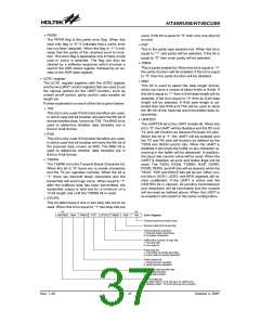
used, if the bit is equal to ²0² then only one stop bit
is used.
The PERR flag is the parity error flag. When this
read only flag is ²0² it indicates that a parity error
has not been detected. When the flag is ²1² it indi-
cates that the parity of the received word is incor-
rect. This error flag is applicable only if Parity mode
(odd or even) is selected. The flag can also be
cleared by a software sequence which involves a
read to the USR status register, followed by an ac-
cess to the RXR data register.
¨
¨
¨
PRT
This is the parity type selection bit. When this bit is
equal to ²1² odd parity will be selected, if the bit is
equal to ²0² then even parity will be selected.
PREN
This is parity enable bit. When this bit is equal to ²1²
the parity function will be enabled, if the bit is equal
to ²0² then the parity function will be disabled.
·
UCR1 register
BNO
The UCR1 register together with the UCR2 register
are the two UART control registers that are used to set
the various options for the UART function, such as
overall on/off control, parity control, data transfer bit
length etc.
This bit is used to select the data length format,
which can have a choice of either 8-bits or 9-bits. If
this bit is equal to ²1² then a 9-bit data length will be
selected, if the bit is equal to ²0² then an 8-bit data
length will be selected. If 9-bit data length is se-
lected then bits RX8 and TX8 will be used to store
the 9th bit of the received and transmitted data re-
spectively.
Further explanation on each of the bits is given below:
¨
TX8
This bit is only used if 9-bit data transfers are used,
in which case this bit location will store the 9th bit of
the transmitted data, known as TX8. The BNO bit is
used to determine whether data transfers are in
8-bit or 9-bit format.
¨
UARTEN
The UARTEN bit is the UART enable bit. When the
bit is ²0² the UART will be disabled and the RX and
TX pins will function as General Purpose I/O pins.
When the bit is ²1² the UART will be enabled and
the TX and RX pins will function as defined by the
TXEN and RXEN control bits. When the UART is
disabled it will empty the buffer so any character re-
maining in the buffer will be discarded. In addition,
the baud rate counter value will be reset. When the
UART is disabled, all error and status flags will be
reset. The TXEN, RXEN, TXBRK, RXIF, OERR,
FERR, PERR, and NF bits will be cleared, while the
TIDLE, TXIF and RIDLE bits will be set. Other con-
trol bits in UCR1, UCR2, and BRG registers will re-
main unaffected. If the UART is active and the
UARTEN bit is cleared, all pending transmissions
and receptions will be terminated and the module
will be reset as defined above. When the UART is
re-enabled it will restart in the same configuration.
¨
RX8
This bit is only used if 9-bit data transfers are used,
in which case this bit location will store the 9th bit of
the received data, known as RX8. The BNO bit is
used to determine whether data transfers are in
8-bit or 9-bit format.
¨
TXBRK
The TXBRK bit is the Transmit Break Character bit.
When this bit is ²0² there are no break characters
and the TX pin operates normally. When the bit is
²1² there are transmit break characters and the
transmitter will send logic zeros. When equal to ²1²
after the buffered data has been transmitted, the
transmitter output is held low for a minimum of a
13-bit length and until the TXBRK bit is reset.
¨
STOPS
This bit determines if one or two stop bits are to be
used. When this bit is equal to ²1² two stop bits are
b
7
b
0
U
A
R
T
E
N
B
N
O
P
R
E
N
P
R
T
S
T
O
P
S
T
X
B
R
K
R
X
8
T
X
8
U
C
R
1
R
e
g
i
s
t
e
r
T
R
r
a
n
s
m
v
m
i
t
d
a
t
a
a
b
i
t
8
(
w
r
i
t
e
o
n
l
y
)
e
c
e
i
e
d
a
t
b
i
t
8
h
(
r
e
a
d
o
n
l
y
)
T
1
0
r
a
n
s
i
t
b
i
r
e
a
k
c
k
a
r
a
c
t
e
c
r
:
:
t
n
r
a
n
s
m
t
b
r
e
a
c
h
a
r
a
t
e
r
s
o
b
r
e
a
h
k
e
c
h
a
r
a
c
t
e
r
s
D
e
f
i
n
t
t
e
s
t
n
u
m
b
e
r
o
f
s
t
o
p
b
i
t
s
1
0
:
:
t
o
w
o
s
t
o
p
b
i
t
s
n
e
s
t
o
p
b
i
t
P
1
0
a
r
i
y
t
y
p
e
b
y
i
t
f
:
:
o
e
d
v
d
p
a
r
i
t
o
r
p
a
r
i
t
y
g
e
n
e
r
a
t
o
r
e
n
p
a
r
i
t
y
f
o
r
p
a
r
i
t
y
g
e
n
e
r
a
t
o
r
P
a
r
i
y
e
n
a
b
l
e
b
i
t
1
0
:
:
p
p
a
a
r
r
i
i
t
t
y
y
f
f
u
n
n
c
c
t
i
i
o
n
e
n
a
b
l
e
d
u
t
o
n
d
i
s
a
s
b
l
e
r
d
N
u
m
b
e
r
o
f
d
a
t
a
t
r
a
n
f
e
b
i
t
s
1
0
:
:
9
8
-
-
b
i
i
t
t
d
d
a
t
t
a
a
t
t
r
a
a
n
s
s
f
f
e
r
b
a
r
n
e
r
U
A
R
T
e
n
e
a
b
l
e
b
i
t
1
0
:
:
e
d
n
i
a
b
l
U
A
R
T
,
T
X
&
R
X
p
i
n
s
a
s
U
A
R
T
p
i
n
s
s
a
b
l
e
U
A
R
T
,
T
X
&
R
X
p
i
n
s
a
s
I
/
O
p
o
r
t
p
i
n
s
Rev. 1.20
37
October 2, 2007

 HOLTEK [ HOLTEK SEMICONDUCTOR INC ]