HT46RU66/HT46CU66
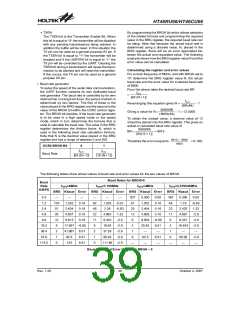
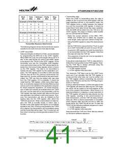
Baud Rates for BRGH=1
fSYS=7.159MHz fSYS=4MHz
BRG Kbaud Error BRG Kbaud Error
Baud
Rate
f
SYS=8MHz
fSYS=3.579545MHz
K/BPS
BRG Kbaud Error
BRG Kbaud Error
0.3
1.2
¾
¾
207
103
51
25
12
8
¾
¾
¾
¾
185
92
46
22
11
7
¾
¾
¾
¾
207
103
51
25
12
6
¾
¾
¾
185
92
46
22
11
5
¾
¾
0.23
0.23
-0.83
1.32
-2.9
-2.9
-2.9
-2.9
¾
1.202
2.404
4.808
9.615
0.16
0.16
0.16
0.16
1.203
2.406
4.76
¾
¾
¾
2.4
2.404
4.808
9.615
0.16
0.16
0.16
2.405
4.811
0.23
0.23
4.8
9.6
9.520 -0.832
19.454 1.32
9.727
18.643
37.286
55.930
111.86
¾
19.2
38.4
57.6
115.2
250
19.231 0.16
38.462 0.16
55.556 -3.55
19.231 0.16
35.714 -6.99
37.287
55.93
111.86
¾
-2.9
-2.9
-2.9
¾
3
62.5
125
250
8.51
8.51
0
3
3
125
250
8.51
0
3
1
1
1
0
¾
¾
Baud Rates and Error Values for BRGH = 1
·
Setting up and controlling the UART
Clearing the UARTEN bit will disable the TX and RX
pins and allow these two pins to be used as normal
I/O pins. When the UART function is disabled the
buffer will be reset to an empty condition, at the
same time discarding any remaining residual data.
Disabling the UART will also reset the error and sta-
tus flags with bits TXEN, RXEN, TXBRK, RXIF,
OERR, FERR, PERR and NF being cleared while
bits TIDLE, TXIF and RIDLE will be set. The re-
maining control bits in the UCR1, UCR2 and BRG
registers will remain unaffected. If the UARTEN bit
in the UCR1 register is cleared while the UART is
active, then all pending transmissions and recep-
tions will be immediately suspended and the UART
will be reset to a condition as defined above. If the
UART is then subsequently re-enabled, it will restart
again in the same configuration.
¨
Introduction
For data transfer, the UART function utilizes a
non-return-to-zero, more commonly known as
NRZ, format. This is composed of one start bit, eight
or nine data bits, and one or two stop bits. Parity is
supported by the UART hardware, and can be
setup to be even, odd or no parity. For the most
common data format, 8 data bits along with no par-
ity and one stop bit, denoted as 8, N, 1, is used as
the default setting, which is the setting at power-on.
The number of data bits and stop bits, along with the
parity, are setup by programming the corresponding
BNO, PRT, PREN, and STOPS bits in the UCR1
register. The baud rate used to transmit and receive
data is setup using the internal 8-bit baud rate gen-
erator, while the data is transmitted and received
LSB first. Although the UART¢s transmitter and re-
ceiver are functionally independent, they both use
the same data format and baud rate. In all cases
stop bits will be used for data transmission.
¨
Data, parity and stop bit selection
The format of the data to be transferred, is com-
posed of various factors such as data bit length,
parity on/off, parity type, address bits and the num-
ber of stop bits. These factors are determined by
the setup of various bits within the UCR1 register.
The BNO bit controls the number of data bits which
can be set to either 8 or 9, the PRT bit controls the
choice of odd or even parity, the PREN bit controls
the parity on/off function and the STOPS bit decides
whether one or two stop bits are to be used. The fol-
lowing table shows various formats for data trans-
mission. The address bit identifies the frame as an
address character. The number of stop bits, which
can be either one or two, is independent of the data
length.
¨
Enabling/disabling the UART
The basic on/off function of the internal UART func-
tion is controlled using the UARTEN bit in the UCR1
register. As the UART transmit and receive pins, TX
and RX respectively, are pin-shared with normal I/O
pins, one of the basic functions of the UARTEN con-
trol bit is to control the UART function of these two
pins. If the UARTEN, TXEN and RXEN bits are set,
then these two I/O pins will be setup as a TX output
pin and an RX input pin respectively, in effect dis-
abling the normal I/O pin function. If no data is being
transmitted on the TX pin then it will default to a
logic high value.
Rev. 1.20
40
October 2, 2007

 HOLTEK [ HOLTEK SEMICONDUCTOR INC ]