HT46RU66/HT46CU66
UART Bus Serial Interface
which can also be used as a general purpose I/O pin,
if the pin is not configured as a receiver, which occurs
if the RXEN bit in the UCR2 register is equal to zero.
Along with the UARTEN bit, the TXEN and RXEN bits,
if set, will automatically setup these I/O pins to their re-
spective TX output and RX input conditions and dis-
able any pull-high resistor option which may exist on
the RX pin.
The HT46RU66/HT46CU66 devices contain an inte-
grated full-duplex asynchronous serial communications
UART interface that enables communication with exter-
nal devices that contain a serial interface. The UART
function has many features and can transmit and re-
ceive data serially by transferring a frame of data with
eight or nine data bits per transmission as well as being
able to detect errors when the data is overwritten or in-
correctly framed. The UART function possesses its own
internal interrupt which can be used to indicate when a
reception occurs or when a transmission terminates.
·
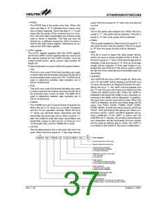
UART data transfer scheme
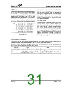
The block diagram shows the overall data transfer
structure arrangement for the UART. The actual data
to be transmitted from the MCU is first transferred to
the TXR register by the application program. The data
will then be transferred to the Transmit Shift Register
from where it will be shifted out, LSB first, onto the TX
pin at a rate controlled by the Baud Rate Generator.
Only the TXR register is mapped onto the MCU Data
Memory, the Transmit Shift Register is not mapped
and is therefore inaccessible to the application pro-
gram.
·
UART features
The integrated UART function contains the following
features:
¨
Full-duplex, asynchronous communication
¨
¨
¨
¨
¨
¨
8 or 9 bits character length
Even, odd or no parity options
Data to be received by the UART is accepted on the
external RX pin, from where it is shifted in, LSB first, to
the Receiver Shift Register at a rate controlled by the
Baud Rate Generator. When the shift register is full,
the data will then be transferred from the shift register
to the internal RXR register, where it is buffered and
can be manipulated by the application program. Only
the RXR register is mapped onto the MCU Data Mem-
ory, the Receiver Shift Register is not mapped and is
therefore inaccessible to the application program.
It should be noted that the actual register for data
transmission and reception, although referred to in the
text, and in application programs, as separate TXR
and RXR registers, only exists as a single shared reg-
ister in the Data Memory. This shared register known
as the TXR/RXR register is used for both data trans-
mission and data reception.
One or two stop bits
Baud rate generator with 8-bit prescaler
Parity, framing, noise and overrun error detection
Support for interrupt on address detect
(last character bit=1)
¨
¨
¨
¨
Separately enabled transmitter and receiver
2-byte Deep Fifo Receive Data Buffer
Transmit and receive interrupts
Interrupts can be initialized by the following
conditions:
-
Transmitter Empty
-
Transmitter Idle
-
Receiver Full
-
Receiver Overrun
-
·
Address Mode Detect
UART status and control registers
There are five control registers associated with the
UART function. The USR, UCR1 and UCR2 registers
control the overall function of the UART, while the
BRG register controls the Baud rate. The actual data
to be transmitted and received on the serial interface
is managed through the TXR/RXR data registers.
·
UART external pin interfacing
To communicate with an external serial interface, the
internal UART has two external pins known as TX and
RX. The TX pin is the UART transmitter pin, which can
be used as a general purpose I/O pin if the pin is not
configured as a UART transmitter, which occurs when
the TXEN bit in the UCR2 control register is equal to
zero. Similarly, the RX pin is the UART receiver pin,
T
r
a
n
s
m
i
t
t
e
r
S
h
i
f
t
R
e
g
i
s
t
e
r
R
e
c
e
i
v
e
r
S
h
i
f
t
R
e
g
i
s
t
e
r
M
S
B
L
S
B
T
X
P
i
n
R
X
P
i
n
M
S
B
L
S
B
C
L
K
C
L
K
T
X
R
R
e
g
i
s
t
e
r
R
X
R
R
e
g
i
s
t
e
r
B
a
u
d
R
a
t
e
G
e
n
e
r
a
t
o
r
B
u
f
f
e
r
M
C
U
D
a
t
a
B
u
s
UART Data Transfer Scheme
Rev. 1.20
35
October 2, 2007

 HOLTEK [ HOLTEK SEMICONDUCTOR INC ]