HT46R64/HT46C64
Options
The following shows the options in the device. All these options should be defined in order to ensure proper functioning
system.
Options
OSC type selection. This option is to decide if an RC or crystal or 32768Hz crystal oscillator is chosen as system
clock.
WDT, RTC and time base clock source selection.
There are three types of selections: system clock/4 or RTC OSC or WDT OSC.
WDT enable/disable selection. WDT can be enabled or disabled by option.
WDT time-out period selection. There are four types of selection: WDT clock source divided by 212/fS~213/fS,
213/fS~214/fS, 214/fS~215/fS or 215/fS~216/fS.
CLR WDT times selection. This option defines the method to clear the WDT by instruction. ²One time² means that
the ²CLR WDT² can clear the WDT. ²Two times² means only if both of the ²CLR WDT1² and ²CLR WDT2² have been
executed, the WDT can be cleared.
Time Base time-out period selection. The Time Base time-out period ranges from 212/fS to 215/fS ²fS² means the clock
source selected by options.
Buzzer output frequency selection. There are eight types of frequency signals for buzzer output: fS/22~fS/29. ²fS²
means the clock source selected by options.
Wake-up selection. This option defines the wake-up capability. External I/O pins (PA only) all have the capability to
wake-up the chip from a HALT by a falling edge (bit option).
Pull-high selection. This option is to decide whether the pull-high resistance is visible or not in the input mode of the
I/O ports. PA, PB and PD can be independently selected (bit option).
I/O pins share with other function selections.
PA0/BZ, PA1/BZ: PA0 and PA1 can be set as I/O pins or buzzer outputs.
LCD common selection.
There are three types of selections: 2 common (1/2 duty) or 3 common (1/3 duty) or 4 common (1/4 duty). If the 4
common is selected, the segment output pin ²SEG32² will be set as a common output.
LCD bias power supply selection.
There are two types of selections: 1/2 bias or 1/3 bias
LCD bias type selection. This option is to determine what kind of bias is selected, R type or C type.
LCD driver clock frequency selection.
There are seven types of frequency signals for the LCD driver circuits: fS/22~fS/28. ²fS² stands for the clock source se-
lection by options.
LCD ON/OFF at HALT selection
LCD Segments as logical output selection, (byte, bit, bit, bit, bit, bit, bit, bit, bit option)
[SEG0~SEG7], SEG8, SEG9, SEG10, SEG11, SEG12, SEG13, SEG14 or SEG15
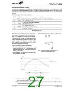
LVR selection. LVR has enable or disable options
LVD selection. LVD has enable or disable options
PFD selection. If PA3 is set as PFD output, there are two types of selections; One is PFD0 as the PFD output, the
other is PFD1 as the PFD output. PFD0, PFD1 are the timer overflow signals of the Timer/Event Counter 0,
Timer/Event Counter 1 respectively.
PWM selection: (7+1) or (6+2) mode
PD0: level output or PWM0 output
PD1: level output or PWM1 output
PD2: level output or PWM2 output
PD3: level output or PWM3 output
INT0 or INT1 trigger edge selection: disable; high to low; low to high; low to high or high to low
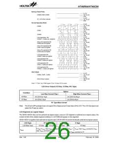
LCD bias current selection: low/high driving current (for R type only).
Rev. 1.80
28
February 14, 2006
图片预览")
 HOLTEK [ HOLTEK SEMICONDUCTOR INC ]