HT46R64/HT46C64
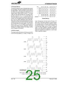
Application Circuits
V
D
D
C
O
M
0
~
C
O
M
2
2
L
C
D
m
0 . 0 1 F *
C
O
M
3
/
S
E
G
3
V
R
D
D
S
P
A
N
E
L
S
E
G
0
~
S
E
G
3
1
1
0
0
k
m
0 . 1 F
E
V
L
C
D
L
C
D
P
o
w
e
r
S
u
p
p
l
y
1
0
k
V
M
A
X
m
0 . 1 F *
V
S
S
C
C
1
2
m
0 . 1 F
V
D
D
R
C
S
y
s
t
e
m
O
s
c
i
l
l
a
t
o
r
3
0
k
W
O
S
C
W
4
7
0
p
F
O
O
S
S
C
C
1
2
O
S
C
V
1
2
O
S
C
1
C
i
r
c
u
i
t
m
0 . 1 F
R
O
S
C
S
Y
S
S
e
e
r
i
g
h
t
s
i
d
e
O
S
C
2
V
C
1
m
0 . 1 F
3
2
7
6
8
H
z
O
S
C
1
C
F
s
r
y
s
t
a
l
S
y
s
t
e
m
O
s
c
i
l
l
a
t
o
r
O
S
C
3
o
r
t
h
e
v
a
l
u
e
s
,
e
e
t
a
b
l
e
b
e
l
o
w
C
2
P
A
0
1
/
B
Z
O
S
C
2
P
A
/
B
Z
O
S
C
4
R
1
P
A
2
P
A
3
/
P
F
D
P
A
4
~
P
A
7
P
D
4
/
I
N
N
T
T
0
1
O
S
C
1
3
2
7
6
8
H
z
C
r
y
s
t
a
l
S
y
s
t
e
m
P
B
0
/
A
N
0
7
O
O
u
s
c
i
l
l
a
t
o
r
P
D
5
/
I
P
B
7
/
A
N
S
C
1
a
n
d
O
S
C
2
l
e
f
t
P
P
D
D
6
7
/
/
T
T
M
M
R
R
0
1
n
c
o
n
n
e
c
t
e
d
P
D
0
/
/
P
W
M
0
O
S
C
2
P
D
3
P
W
M
3
H
T
4
6
R
6
4
/
H
T
4
6
C
6
4
O
S
C
C
i
r
c
u
i
t
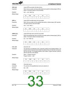
The following table shows the C1, C2 and R1 values corresponding to the different crystal values. (For reference only)
Crystal or Resonator
4MHz Crystal
C1, C2
0pF
R1
10kW
12kW
10kW
10kW
10kW
27kW
9.1kW
10kW
10kW
4MHz Resonator
10pF
0pF
3.58MHz Crystal
3.58MHz Resonator
2MHz Crystal & Resonator
1MHz Crystal
25pF
25pF
35pF
300pF
300pF
300pF
480kHz Resonator
455kHz Resonator
429kHz Resonator
The function of the resistor R1 is to ensure that the oscillator will switch off should low voltage condi-
tions occur. Such a low voltage, as mentioned here, is one which is less than the lowest value of the
MCU operating voltage. Note however that if the LVR is enabled then R1 can be removed.
Note: The resistance and capacitance for reset circuit should be designed in such a way as to ensure that the VDD is
stable and remains within a valid operating voltage range before bringing RES to high.
²*² Make the length of the wiring, which is connected to the RES pin as short as possible, to avoid noise
interference.
²VMAX² connect to VDD or VLCD or V1 refer to the table.
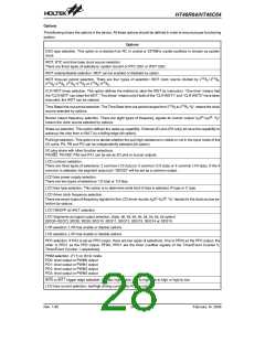
LCD Type
R Type
1/2 bias 1/3 bias
C Type
1/3 bias
LCD bias type
1/2 bias
If VDD>VLCD, then VMAX connect to VDD
,
If VDD > 3/2VLCD, then VMAX connect to VDD
,
VMAX
else VMAX connect to VLCD
else VMAX connect to V1
Rev. 1.80
29
February 14, 2006
图片预览")
 HOLTEK [ HOLTEK SEMICONDUCTOR INC ]