HT46R23/HT46C23
Timer/Event Counter
In the pulse width measurement mode with the TON and
TE bits equal to one, once the TMR has received a tran-
sient from low to high (or high to low if the TE bits is ²0²)
it will start counting until the TMR returns to the original
level and resets the TON. The measured result will re-
main in the timer/event counter even if the activated
transient occurs again. In other words, only one cycle
measurement can be done. Until setting the TON, the
cycle measurement will function again as long as it re-
ceives further transient pulse. Note that, in this operat-
ing mode, the timer/event counter starts counting not
according to the logic level but according to the transient
edges. In the case of counter overflows, the counter is
reloaded from the timer/event counter preload register
and issues the interrupt request just like the other two
modes. To enable the counting operation, the timer ON
bit (TON; bit 4 of TMRC) should be set to 1. In the pulse
width measurement mode, the TON will be cleared au-
tomatically after the measurement cycle is completed.
But in the other two modes the TON can only be reset by
instructions. The overflow of the timer/event counter is
one of the wake-up sources. No matter what the opera-
tion mode is, writing a 0 to ETI can disable the interrupt
service.
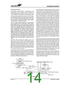
A timer/event counter (TMR) is implemented in the
microcontroller. The timer/event counter contains an
16-bit programmable count-up counter and the clock
may come from an external source or the system clock.
Using the internal system clock, there is only one refer-
ence time-base. The internal clock source comes from
fSYS. The external clock input allows the user to count
external events, measure time intervals or pulse widths,
or to generate an accurate time base.
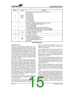
There are three registers related to the timer/event
counter; TMRH (0CH), TMRL (0DH), TMRC (0EH).
Writing TMRL will only put the written data to an internal
lower-order byte buffer (8 bits) and writing TMRH will
transfer the specified data and the contents of the
lower-order byte buffer to TMRH and TMRL preload reg-
isters, respectively. The timer/event counter preload
register is changed by each writing TMRH operations.
Reading TMRH will latch the contents of TMRH and
TMRL counters to the destination and the lower-order
byte buffer, respectively. Reading the TMRL will read the
contents of the lower-order byte buffer. The TMRC is the
timer/event counter control register, which defines the
operating mode, counting enable or disable and active
edge.
In the case of timer/event counter OFF condition, writing
data to the timer/event counter preload register will also
reload that data to the timer/event counter. But if the
timer/event counter is turned on, data written to it will
only be kept in the timer/event counter preload register.
The timer/event counter will still operate until overflow
occurs. When the timer/event counter (reading TMRH)
is read, the clock will be blocked to avoid errors. As
clock blocking may results in a counting error, this must
be taken into consideration by the programmer.
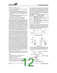
The TM0, TM1 bits define the operating mode. The
event count mode is used to count external events,
which means the clock source comes from an external
(TMR) pin. The timer mode functions as a normal timer
with the clock source coming from the fINT clock. The
pulse width measurement mode can be used to count the
high or low level duration of the external signal (TMR).
The counting is based on the fINT
.
In the event count or timer mode, once the timer/event
counter starts counting, it will count from the current con-
tents in the timer/event counter to FFFFH. Once overflow
occurs, the counter is reloaded from the timer/event coun-
ter preload register and generates the interrupt request
flag (TF; bit 5 of INTC0) at the same time.
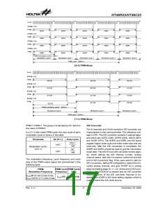
The bit0~bit2 of the TMRC can be used to define the
pre-scaling stages of the internal clock sources of the
timer/event counter. The definitions are as shown. The
overflow signal of the timer/event counter can be used
to generate the PFD signal.
P
W
M
(
6
+
2
)
o
r
(
7
+
1
)
T
o
P
D
0
/
P
D
1
C
i
r
c
u
i
t
C
o
m
p
a
r
e
D
a
t
a
B
u
s
f
S Y S
8
-
s
t
a
g
e
p
r
e
s
c
a
l
e
r
L
o
w
B
y
t
e
f
I N T
B
u
f
f
e
r
8
-
1
M
U
X
T
M
1
T
M
0
P
S
C
2
~
P
S
C
0
T
M
R
1
6
-
B
i
t
R
e
l
o
a
d
P
r
e
l
o
a
d
R
e
g
i
s
t
e
r
T
E
P
u
l
s
e
W
i
d
t
h
O
v
e
r
f
l
o
w
t
o
I
n
t
e
r
r
u
p
t
H
i
g
h
B
y
t
e
L
o
w
B
y
t
e
T
M
1
M
e
a
s
u
r
e
m
e
n
t
T
M
0
M
o
d
e
C
o
n
t
r
o
l
1
6
-
B
i
t
T
i
m
e
r
/
E
v
e
n
t
C
o
u
n
t
e
r
T
O
N
1
/
2
P
F
D
Timer/Event Counter
Rev. 2.11
14
December 29, 2008
图片预览")
 HOLTEK [ HOLTEK SEMICONDUCTOR INC ]