HT46R12
M
i
n
i
m
u
m
o
n
e
i
n
s
t
r
u
c
t
i
o
n
c
y
c
l
e
n
e
e
d
e
d
,
M
a
x
i
m
u
m
t
e
n
i
n
s
t
r
u
c
t
i
o
n
c
y
c
l
e
s
a
l
l
o
w
e
d
S
T
A
R
T
E
O
C
B
A
/
D
s
a
m
p
l
i
n
g
t
i
m
e
A
/
D
s
a
m
p
l
i
n
g
t
i
m
e
A
/
D
s
a
m
p
l
i
n
g
t
i
m
e
t
A
D
C
S
t
A
D
C
S
t
A D C S
P
C
R
2
~
0
0
0
B
1
0
0
B
1
0
1
B
0
0
0
B
1
0
0
B
P
C
R
0
1
.
P
A
t
B
p
o
r
t
s
e
e
t
u
p
a
s
I
/
O
s
2
.
/
D
c
o
n
v
e
r
t
e
r
i
s
p
o
w
e
r
e
d
o
f
f
o
r
e
d
u
c
p
o
w
e
r
c
o
n
s
u
m
p
t
i
o
n
A
C
S
2
~
d
o
n
'
t
c
a
r
e
0
0
0
B
0
0
0
B
0
0
1
B
0
1
0
B
A
C
S
0
P
o
w
e
r
-
o
n
S
t
a
r
t
o
f
A
/
D
S
t
a
r
t
o
f
A
/
D
S
t
a
r
t
o
f
A
/
D
R
e
s
e
t
c
o
n
v
e
r
s
i
o
n
c
o
n
v
e
r
s
i
o
n
c
o
n
v
e
r
s
i
o
n
R
e
s
e
t
A
/
D
R
e
s
e
t
A
/
D
R
e
s
e
t
A
/
D
c
o
n
v
e
r
t
e
r
c
o
n
v
e
r
t
e
r
c
o
n
v
e
r
t
e
r
E
n
d
o
f
A
/
D
E
n
d
o
f
A
/
D
E
n
d
o
f
A
/
D
c
o
n
v
e
r
s
i
o
n
c
o
n
v
e
r
s
i
o
n
c
o
n
v
e
r
s
i
o
n
1
:
D
e
f
i
n
e
P
B
c
o
n
f
i
g
u
r
a
t
i
o
n
2
:
S
e
l
e
c
t
a
n
a
l
o
g
c
h
a
n
n
e
l
t
A
D
C
t
A
D
C
t
A D C
A
/
D
c
o
n
v
e
r
s
i
o
n
t
i
m
e
A
/
D
c
o
n
v
e
r
s
i
o
n
t
i
m
e
A
/
D
c
o
n
v
e
r
s
i
o
n
t
i
m
e
N
o
t
e
:
A
/
D
c
l
o
c
k
m
u
s
t
b
e
f
S
Y
S
/
2
,
f
S
Y
S
/
8
o
r
f
S
Y
S
/
3
2
t
t
A
D
C
S
A
D
A
D
C
A
D
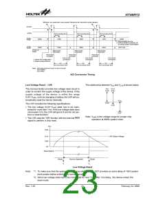
A/D Conversion Timing
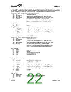
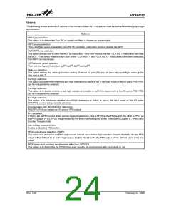
Low Voltage Reset - LVR
The relationship between VDD and VLVR is shown below.
V
D
D
V
O P R
The microcontroller provides low voltage reset circuit in
order to monitor the supply voltage of the device. If the
supply voltage of the device is within the range
0.9V~VLVR, such as changing a battery, the LVR will au-
tomatically reset the device internally.
5
.
5
V
5
.
5
V
V
L
V
R
3
.
0
V
The LVR includes the following specifications:
2
.
2
V
·
The low voltage (0.9V~VLVR) state has to be main-
tained for more than 1ms. If the low voltage state does
not exceed 1ms, the LVR will ignore it and do not per-
form a reset function.
0
.
9
V
Note: VOPR is the voltage range for proper chip
operation at 4MHz system clock.
·
The LVR uses the ²OR² function with the external RES
signal to perform a chip reset.
V
D
D
5
.
5
V
L
V
R
D
e
t
e
c
t
V
o
l
t
a
g
e
V
L
V
R
0
.
9
0
V
V
R
e
s
e
t
S
i
g
n
a
l
R
e
s
e
t
N
o
r
m
a
l
O
p
e
r
a
t
i
o
n
R
e
s
e
t
*
1
*
2
Low Voltage Reset
Note: *1: To make sure that the system oscillator has stabilized, the SST provides an extra delay of 1024 system
clock pulses before entering the normal operation.
*2: Since low voltage state has to be maintained for over 1ms, after 1ms delay, the device enters the
reset mode.
Rev. 1.20
23
February 24, 2006
图片预览")
 HOLTEK [ HOLTEK SEMICONDUCTOR INC ]