HT46R064B/065B/066B
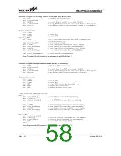
When an interrupt request is generated it takes 2 or 3 in-
struction cycle before the program jumps to the interrupt
vector. If the device is in the Sleep or Idle Mode and is
woken up by an interrupt request then it will take 3 cy-
cles before the program jumps to the interrupt vector.
In cases where both external and internal interrupts are
enabled and where an external and internal interrupt oc-
curs simultaneously, the external interrupt will always
have priority and will therefore be serviced first. Suitable
masking of the individual interrupts using the interrupt
registers can prevent simultaneous occurrences.
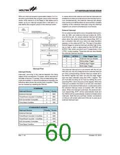
Main
Program
External Interrupt
Interrupt Request or
Interrupt Flag Set by Instruction
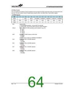
For an external interrupt to occur, the global interrupt en-
able bit, EMI, and external interrupt enable bit, INTE,
must first be set. An actual external interrupt will take
place when the external interrupt request flag, INTF, is
set, a situation that will occur when an edge transition
appears on the external INT line. The type of transition
that will trigger an external interrupt, whether high to low,
low to high or both is determined by the INTEG0 and
INTEG1 bits, which are bits 6 and 7 respectively, in the
CTRL1 control register. These two bits can also disable
the external interrupt function.
N
Enable Bit Set ?
Y
Main
Automatically Disable Interrupt
Program
Clear EMI & Request Flag
Wait for 2 ~ 3 Instruction Cycles
ISR Entry
INTEG1
INTEG0
Edge Trigger Type
External interrupt disable
Rising edge Trigger
Falling edge Trigger
Both edge Trigger
0
0
1
1
0
1
0
1
RETI
(it will set EMI automatically)
Interrupt Flow
The external interrupt pin is pin-shared with the I/O pin
PA3 and can only be configured as an external interrupt
pin if the corresponding external interrupt enable bit in
the INTC0 register has been set and the edge trigger
type has been selected using the CTRL1 register. The
pin must also be setup as an input by setting the corre-
sponding PAC.3 bit in the port control register. When the
interrupt is enabled, the stack is not full and a transition
appears on the external interrupt pin, a subroutine call to
the external interrupt vector at location 04H, will take
place. When the interrupt is serviced, the external inter-
rupt request flag, INTF, will be automatically reset and
the EMI bit will be automatically cleared to disable other
interrupts. Note that any pull-high resistor connections
on this pin will remain valid even if the pin is used as an
external interrupt input.
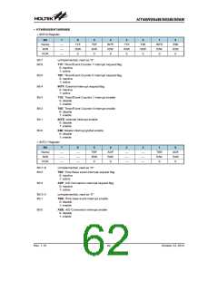
Interrupt Priority
Interrupts, occurring in the interval between the rising
edges of two consecutive T2 pulses, will be serviced on
the latter of the two T2 pulses, if the corresponding inter-
rupts are enabled. In case of simultaneous requests, the
following table shows the priority that is applied. These
can be masked by resetting the EMI bit.
HT46R064B
Interrupt Source
Priority Vector
External Interrupt
1
2
3
4
04H
08H
0CH
10H
Timer/Event Counter 0 Overflow
A/D Conversion Complete
Time Base Overflow
HT46R065B/HT46R066B
Interrupt Source
Priority Vector
External Interrupt
1
2
3
4
5
04H
08H
0CH
10H
14H
Timer/Event Counter 0 Overflow
Timer/Event Counter 1 Overflow
A/D Conversion Complete
Time Base Overflow
Rev. 1.10
60
October 23, 2012

 HOLTEK [ HOLTEK SEMICONDUCTOR INC ]