HT46R064B/065B/066B
Timer/Event Counter Interrupt
All of these interrupts have the capability of waking up
the processor when in the Idle/Sleep Mode.
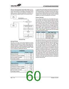
For a Timer/Event Counter interrupt to occur, the global
interrupt enable bit, EMI, and the corresponding timer
interrupt enable bit, TnE, must first be set. An actual
Timer/Event Counter interrupt will take place when the
Timer/Event Counter request flag, TnF, is set, a situation
that will occur when the relevant Timer/Event Counter
overflows. When the interrupt is enabled, the stack is
not full and a Timer/Event Counter n overflow occurs, a
subroutine call to the relevant timer interrupt vector, will
take place. When the interrupt is serviced, the timer in-
terrupt request flag, TnF, will be automatically reset and
the EMI bit will be automatically cleared to disable other
interrupts.
Only the Program Counter is pushed onto the stack. If
the contents of the register or status register are altered
by the interrupt service program, which may corrupt the
desired control sequence, then the contents should be
saved in advance.
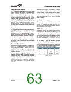
SCOM Function for LCD
The devices have the capability of driving external LCD
panels. The common pins for LCD driving, SCOM0~
SCOM3, are pin shared with certain pin on the PB0~
PB3 port. The LCD signals (COM and SEG) are gener-
ated using the application program.
Time Base Interrupt
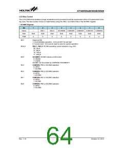
LCD Operation
For a time base interrupt to occur the global interrupt en-
able bit EMI and the corresponding interrupt enable bit
TBE, must first be set. An actual Time Base interrupt will
take place when the time base request flag TBF is set, a
situation that will occur when the Time Base overflows.
When the interrupt is enabled, the stack is not full and a
time base overflow occurs a subroutine call to time base
vector will take place. When the interrupt is serviced, the
time base interrupt flag. TBF will be automatically reset
and the EMI bit will be automatically cleared to disable
other interrupts.
An external LCD panel can be driven using this device
by configuring the PB0~PB3 pins as common pins and
using other output ports lines as segment pins. The LCD
driver function is controlled using the SCOMC register
which in addition to controlling the overall on/off function
also controls the bias voltage setup function. This en-
ables the LCD COM driver to generate the necessary
V
DD/2 voltage levels for LCD 1/2 bias operation.
The SCOMEN bit in the SCOMC register is the overall
master control for the LCD Driver, however this bit is
used in conjunction with the COMnEN bits to select
which Port B pins are used for LCD driving. Note that the
Port Control register does not need to first setup the pins
as outputs to enable the LCD driver operation.
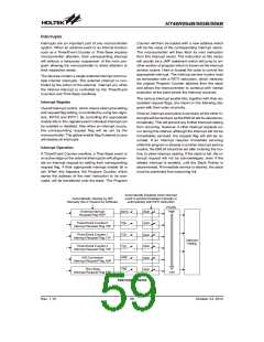
Programming Considerations
By disabling the interrupt enable bits, a requested inter-
rupt can be prevented from being serviced, however,
once an interrupt request flag is set, it will remain in this
condition in the interrupt register until the corresponding
interrupt is serviced or until the request flag is cleared by
a software instruction.
SCOMEN COMnEN Pin Function O/P Level
0
1
1
X
0
1
I/O
I/O
0 or 1
0 or 1
It is recommended that programs do not use the ²CALL
subroutine² instruction within the interrupt subroutine.
Interrupts often occur in an unpredictable manner or
need to be serviced immediately in some applications. If
only one stack is left and the interrupt is not well con-
trolled, the original control sequence will be damaged
once a ²CALL subroutine² is executed in the interrupt
subroutine.
SCOMN
VDD/2
Output Control
Rev. 1.10
63
October 23, 2012

 HOLTEK [ HOLTEK SEMICONDUCTOR INC ]