HT37B90/HT37B70/HT37B50/HT37B30
Special Vectors
Within the Program Memory, certain locations are re-
served for special usage such as reset and interrupts.
·
·
Location 000H
This vector is reserved for use by the device reset for
program initialization. After a device reset is initiated,
the program will jump to this location and begin execu-
tion.
Location 004H
This vector is used by the external interrupt. If the ex-
ternal interrupt pin on the device goes low, the pro-
gram will jump to this location and begin execution if
the external interrupt is enabled and the stack is not
full.
If the stack is full and an enabled interrupt takes place,
the interrupt request flag will be recorded but the ac-
knowledge signal will be inhibited. When the Stack
Pointer is decremented, by RET or RETI, the interrupt
will be serviced. This feature prevents stack overflow al-
lowing the programmer to use the structure more easily.
However, when the stack is full, a CALL subroutine in-
struction can still be executed which will result in a stack
overflow. Precautions should be taken to avoid such
cases which might cause unpredictable program
branching.
·
·
·
Location 008H
This vector is reserved for the Timer/Event Counter 0
interrupt service program. If a timer interrupt results
from a Timer/Event Counter 0 overflow, and if the in-
terrupt is enabled and the stack is not full, the program
begins execution at location 008H.
Location 00CH
This vector is reserved for the Timer/Event Counter 1
interrupt service program. If a timer interrupt results
from a Timer/Event Counter 1 overflow, and if the in-
terrupt is enabled and the stack is not full, the program
begins execution at location 00CH.
Arithmetic and Logic Unit - ALU
The arithmetic-logic unit or ALU is a critical area of the
microcontroller that carries out arithmetic and logic op-
erations of the instruction set. Connected to the main
microcontroller data bus, the ALU receives related in-
struction codes and performs the required arithmetic or
logical operations after which the result will be placed in
the specified register. As these ALU calculation or oper-
ations may result in carry, borrow or other status
changes, the status register will be correspondingly up-
dated to reflect these changes. The ALU supports the
following functions:
Location 010H
This vector is reserved for the Timer Counter 2 inter-
rupt service program. If a timer interrupt results from a
Timer Counter 2 overflow, and if the interrupt is en-
abled and the stack is not full, the program begins ex-
ecution at location 0010H. Timer 2 Counter overflow
interrupt share with UART interrupt require. Using the
UART interrupt require is defined by enabled UART
function enable configuration option.
·
·
·
Arithmetic operations: ADD, ADDM, ADC, ADCM,
SUB, SUBM, SBC, SBCM, DAA
·
·
Location 014H
This vector is reserved for the ERCOCI interrupt ser-
vice program. If an external RC oscillation converter
interrupt results from an external RC oscillation con-
verter interrupt is activated, and the stack is not full,
the program begins execution at location 0014H.
Logic operations: AND, OR, XOR, ANDM, ORM,
XORM, CPL, CPLA
Rotation RRA, RR, RRCA, RRC, RLA, RL, RLCA,
RLC
·
·
Increment and Decrement INCA, INC, DECA, DEC
Location 018H
This vector is reserved for the Adpcm interrupt service
program. If a Adpcm interrupt results, and if the inter-
rupt is enabled and the stack is not full, the program
begins execution at location 0018H.
Branch decision, JMP, SZ, SZA, SNZ, SIZ, SDZ,
SIZA, SDZA, CALL, RET, RETI
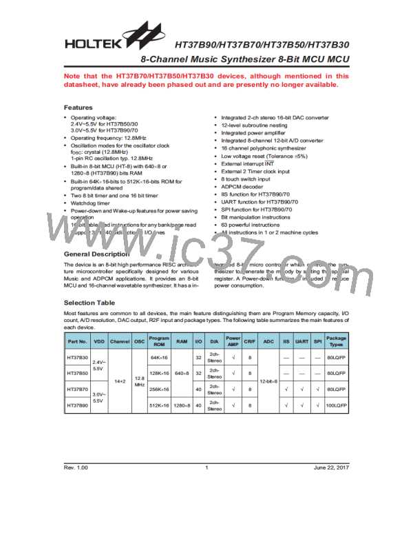
Program Memory
The Program Memory is the location where the user
code or program is stored. The type of memory is the
mask ROM memory. It offer the most cost effective solu-
tions for high volume products.
Structure
The Program Memory has a capacity of 512K by 16,
256K by 16, 128K by 16 or 64K by 16 bits depending
upon which device is selected.
Rev. 1.00
11
June 22, 2017

 HOLTEK [ HOLTEK SEMICONDUCTOR INC ]