HT46R4A
If the system is woken up by an interrupt, then two possi-
ble situations may occur. The first is where the related
interrupt is disabled or the interrupt is enabled but the
stack is full, in which case the program will resume exe-
cution at the instruction following the ²HALT² instruction.
In this situation, the interrupt which woke-up the device
will not be immediately serviced, but will rather be ser-
viced later when the related interrupt is finally enabled or
when a stack level becomes free. The other situation is
where the related interrupt is enabled and the stack is
not full, in which case the regular interrupt response
takes place. If an interrupt request flag is set to ²1² be-
fore entering the Power Down Mode, the wake-up func-
tion of the related interrupt will be disabled.
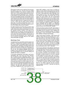
internal WDT oscillator, or from fSYS/4, it is further di-
vided by 16 via an internal 15-bit counter and a clearable
single bit counter to give longer Watchdog time-outs. As
this ratio is fixed it gives an overall Watchdog Timer
time-out value of 215/fS to 216/fS. As the clear instruction
only resets the last stage of the divider chain, for this
reason the actual division ratio and corresponding
Watchdog Timer time-out can vary by a factor of two.
The exact division ratio depends upon the residual value
in the Watchdog Timer counter before the clear instruc-
tion is executed. It is important to realise that as there
are no independent internal registers or configuration
options associated with the length of the Watchdog
Timer time-out, it is completely dependent upon the fre-
quency of fSYS/4 or the internal WDT oscillator.
No matter what the source of the wake-up event is, once
a wake-up situation occurs, a time period equal to 1024
system clock periods will be required before normal sys-
tem operation resumes. However, if the wake-up has
originated due to an interrupt, the actual interrupt sub-
routine execution will be delayed by an additional one or
more cycles. If the wake-up results in the execution of
the next instruction following the ²HALT² instruction, this
will be executed immediately after the 1024 system
clock period delay has ended.
If the fSYS/4 clock is used as the WDT clock source, it
should be noted that when the system enters the Power
Down Mode, then the instruction clock is stopped and
the WDT will lose its protecting purposes. For systems
that operate in noisy environments, using the internal
WDT oscillator is strongly recommended.
Under normal program operation, a WDT time-out will
initialise a device reset and set the status bit TO. How-
ever, if the system is in the Power Down Mode, when a
WDT time-out occurs, the TO bit in the status register
will be set and only the Program Counter and Stack
Pointer will be reset. Three methods can be adopted to
clear the contents of the WDT. The first is an external
hardware reset, which means a low level on the RES
pin, the second is using the watchdog software instruc-
tions and the third is via a ²HALT² instruction.
Watchdog Timer
The Watchdog Timer is provided to prevent program mal-
functions or sequences from jumping to unknown loca-
tions, due to certain uncontrollable external events such
as electrical noise. It operates by providing a device reset
when the WDT counter overflows. The WDT clock is sup-
plied by one of two sources selected by configuration op-
tion: its own self contained dedicated internal WDT
oscillator or fSYS/4. Note that if the WDT configuration op-
tion has been disabled, then any instruction relating to its
operation will result in no operation.
There are two methods of using software instructions to
clear the Watchdog Timer, one of which must be chosen
by configuration option. The first option is to use the sin-
gle ²CLR WDT² instruction while the second is to use the
two commands ²CLR WDT1² and ²CLR WDT2². For the
first option, a simple execution of ²CLR WDT² will clear
the WDT while for the second option, both ²CLR WDT1²
and ²CLR WDT2² must both be executed to successfully
clear the WDT. Note that for this second option, if ²CLR
WDT1² is used to clear the WDT, successive executions
of this instruction will have no effect, only the execution of
a ²CLR WDT2² instruction will clear the WDT. Similarly
after the ²CLR WDT2² instruction has been executed,
only a successive ²CLR WDT1² instruction can clear the
Watchdog Timer.
In the device, all Watchdog Timer options, such as en-
able/disable, WDT clock source and clear instruction
type all selected through configuration options. There
are no internal registers associated with the WDT in the
Cost-Effective A/D Type MCU series. One of the WDT
clock sources is an internal oscillator which has an ap-
proximate period of 65ms at a supply voltage of 5V. How-
ever, it should be noted that this specified internal clock
period can vary with VDD, temperature and process
variations. The other WDT clock source option is the
f
SYS/4 clock. Whether the WDT clock source is its own
C
C
L
L
R
R
W
W
D
D
T
T
1
2
F
F
l
l
a
a
g
g
C
l
e
a
r
W
D
T
T
y
p
e
C
o
n
f
i
g
u
r
a
t
i
o
n
O
p
t
i
o
n
1
o
r
2
I
n
s
t
r
u
c
t
i
o
n
s
C
L
R
W
D
T
C
l
o
c
k
S
o
u
r
c
e
S
Y
S
f
S
W
D
T
T
i
m
e
-
o
u
t
C
o
n
f
i
g
u
r
a
t
i
o
n
1
5
-
b
i
t
C
o
u
n
t
e
r
¸
2
1
5
1
6
2
/
f
S
~
2
/
f
W
D
T
O
s
c
i
l
l
a
t
o
r
O
p
t
i
o
n
W
D
T
C
l
o
c
k
S
o
u
r
c
e
Watchdog Timer
Rev. 1.00
38
November 28, 2007

 HOLTEK [ HOLTEK SEMICONDUCTOR INC ]