HT48RA0-3/HT48CA0-3
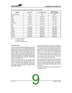
A.C. Characteristics
Ta=25°C
Test Conditions
Conditions
Symbol
Parameter
Min.
Typ.
Max.
Unit
VDD
fSYS=4MHz(±3%) ,
fSYS
System Clock
3V
3880
4000
1024
4120
kHz
tSYS
Temp. = 0°C ~ +50°C
Power-up, reset or wake-up
from HALT
tSST
System Start-up Timer Period
¾
¾
¾
tLVR
tPOR
Low Voltage Width to Reset
0.25
1
1
2
ms
¾
¾
¾
¾
Power-on Reset Low Pulse Width
¾
¾
ms
Note: tSYS=1/fSYS
Functional Description
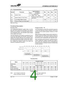
Execution Flow
Program Counter - PC
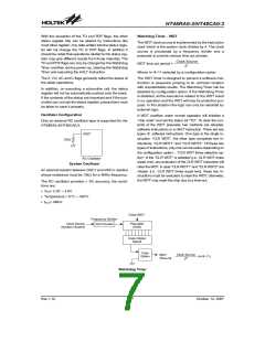
The HT48RA0-3/HT48CA0-3 system clock is an RC
type clock which requires the connection of an external
resistor for its operation. It is internally divided into four
non-overlapping clocks. One instruction cycle consists
of four system clock cycles.
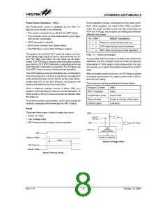
The 10-bit program counter (PC) controls the sequence
in which the instructions stored in program memory are
executed and its contents specify a maximum of 1024
addresses.
After accessing a program memory word to fetch an in-
struction code, the contents of the program counter are
incremented by one. The program counter then points to
the memory word containing the next instruction code.
Instruction fetching and execution are pipelined in such
a way that a fetch takes one instruction cycle while de-
coding and execution takes the next instruction cycle.
However, the pipelining scheme causes each instruc-
tion to effectively execute within one cycle. If an instruc-
tion changes the program counter, two cycles are
required to complete the instruction.
When executing a jump instruction, conditional skip ex-
ecution, loading PCL register, subroutine call, initial re-
set or return from subroutine, the PC manipulates the
program transfer by loading the address corresponding
to each instruction.
T
1
T
2
T
3
T
4
T
1
T
2
T
3
T
4
T
1
T
2
T
3
T
4
S
y
s
t
e
m
C
l
o
c
k
I
n
s
t
r
u
c
t
i
o
n
C
y
c
l
e
P
C
P
C
+
1
P
C
+
2
P
C
F
e
t
c
h
I
N
S
T
(
P
C
)
E
x
e
c
u
t
e
I
N
S
T
(
P
C
-
1
)
F
e
t
c
h
I
N
S
T
(
P
C
+
1
)
E
x
e
c
u
t
e
I
N
S
T
(
P
C
)
F
e
t
c
h
I
N
S
T
(
P
C
+
2
)
E
x
e
c
u
t
e
I
N
S
T
(
P
C
+
1
)
Execution Flow
Program Counter
Mode
Initial reset
*9
*8
*7
*6
*5
*4
*3
*2
*1
*0
0
0
0
0
0
0
0
0
0
0
Skip
Program Counter + 2
Loading PCL
Jump, call branch
*9
*8
@7
#7
@6
#6
@5
#5
@4
#4
@3
#3
@2
#2
@1
#1
@0
#0
#9
#8
S8
Return from subroutine
S9
S7
S6
S5
S4
S3
S2
S1
S0
Program Counter
Note: *9~*0: Program counter bits
#9~#0: Instruction code bits
S9~S0: Stack register bits
@7~@0: PCL bits
Rev.1.10
4
October 12, 2007

 HOLTEK [ HOLTEK SEMICONDUCTOR INC ]