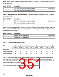
Bit 1—Input Buffer Full (IBF): Set to 1 when the host processor writes to IDR1. This bit is an
internal interrupt source to the slave processor. IBF is cleared to 0 when the slave processor reads
IDR1.
Bit 1: IBF
Description
0
1
This bit is cleared when the slave processor reads IDR1
This bit is set when the host processor writes to IDR1
(Initial value)
Bit 0—Output Buffer Full (OBF): Set to 1 when the slave processor writes to ODR1. Cleared to
0 when the host processor reads ODR1.
Bit 0: OBF
Description
0
1
This bit is cleared when the host processor reads ODR1
This bit is set when the slave processor writes to ODR1
(Initial value)
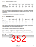
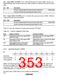
Table 14.3 shows the conditions for setting and clearing the STR1 flags.
Table 14.3 Set/Clear Timing for STR1 Flags
Flag
Setting Condition
Clearing Condition
C/D
Rising edge of host’s write signal (IOW)
when HA0 is high
Rising edge of host’s write signal (IOW)
when HA0 is low
IBF
Rising edge of host’s write signal (IOW)
when writing to IDR1
Falling edge of slave’s internal read signal
(RD) when reading IDR1
OBF
Falling edge of slave’s internal write
signal (WR) when writing to ODR1
Rising edge of host’s read signal (IOR)
when reading ODR1
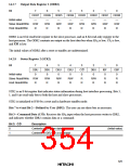
14.2.6 Input Data Register 2 (IDR2)
Bit
7
IDR7
—
6
IDR6
—
5
IDR5
—
4
IDR4
—
3
IDR3
—
2
IDR2
—
1
IDR1
—
0
IDR0
—
Initial value
Slave ead/WrRite
Host Read/Write
RRRRRRRR
W
W
W
W
W
W
W
W
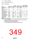
IDR2 is an 8-bit read-only register to the slave processor, and an 8-bit write-only register to the
host processor. When CS2 is low, information on the host data bus is written into IDR2 at the
rising edge of IOW. The HA0 state is also latched into the C/D bit in STR2 to indicate whether the
written information is a command or data.
The initial values of IDR2 after a reset or standby are undetermined.
324

 HITACHI [ HITACHI SEMICONDUCTOR ]