13.3
Operation
13.3.1 I2C Bus Data Format
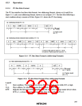
The I2C bus interface has three data formats: two addressing formats, shown as (a) and (b) in
figure 13.3, and a non-addressing format, shown as (c) in figure 13.4. The first byte following a
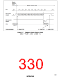
start condition always consists of 8 bits. Figure 13.5 shows the I2C bus timing.
(a) Addressing format (FS = 0)
S
1
SLA
7
R/W
A
1
DATA
n
A
1
A/A
P
1
n: Bit count
(n = 1 to 8)
1
1
m
m: Frame count
(m ≥ 1)
1
(b) Addressing format (retransmit start condition, FS = 0)
S
1
SLA
7
R/W
A
1
DATA
n1
A/A
S
1
SLA
7
R/W
A
1
DATA
n2
A/A
P
1
1
1
1
1
m1
m2
1
1
n1 and n2: Bit count (n1 and n2 = 1 to 8)
m1 and m2: Frame count (m1 and m2 ≥ 1)
Figure 13.3 I2C Bus Data Formats (Addressing Formats)
(c) Non-addressing format (FS = 1)
S
1
DATA
8
A
1
DATA
n
A
1
A/A
P
1
n: Bit count
(n = 1 to 8)
1
m
m: Frame count
(m ≥ 1)
1
Figure 13.4 I2C Bus Data Format (Non-Addressing Format)
Legend:
S:
SLA:
R/W:
Start condition. The master device drives SDA from high to low while SCL is high.
Slave address, by which the master device selects a slave device.
Indicates the direction of data transfer: from the slave device to the master device when
R/W is 1, or from the master device to the slave device when R/W is 0.
297

 HITACHI [ HITACHI SEMICONDUCTOR ]