CA3060
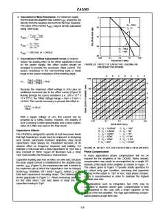
decreased to maintain the same value of source current. and 3 is shown in Figure 27 and a typical circuit is shown in
The low cost dual gate protected MOSFET, 40841 type, may Figure 28. The multiplier consists of a single CA3060 and,
be used when operating at the low supply voltage.
as in the two quadrant multiplier, exhibits no level shift
between input and output. In Figure 27, Amplifier 1 is
connected as an inverting amplifier for the X-input signal.
The output current of Amplifier 1 is calculated as follows:
The phase compensation network consists of a single 390Ω
resistor and a 1000pF capacitor, located at the interface of the
CA3060 output and the MOSFET gate. The bandwidth of the
system is 1.5MHz and the slew rate is 0.3V/µs. The system
slew rate is directly proportional to the value of the phase
compensation capacitor. Thus, with higher gain settings
where lower values of phase compensation capacitors are
possible, the slew rate is proportionally increased.
I (1) = [-V ] [g (1)]
21
EQ. 1
O
X
Amplifier 2 is a non-inverting amplifier so that
IO(2) = [+VX] [g (2)]
EQ. 2
21
Because the amplifier output impedances are high, the load
current is the sum of the two output currents, for an output
voltage
Non-Linear Applications
AM Modulator (Two Quadrant Multiplier)
V
= V R [g (2) - g (1)]
21 21
EQ. 3
O
X L
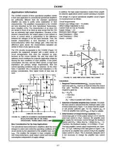
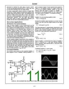
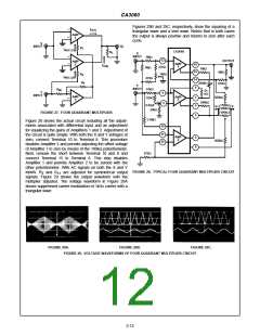
Figure 26 shows Amplifier 3 of the CA3060 used in an AM
modulator or two quadrant multiplier circuit. When modula-
tion is applied to the amplifier bias input, Terminal B, and the
carrier frequency to the differential input, Terminal A, the
waveform, shown in Figure 26 is obtained. Figure 26 is a
result of adjusting the input offset control to balance the
circuit so that no modulation can occur at the output without
a carrier input. The linearity of the modulator is indicated by
the solid trace of the superimposed modulating frequency.
The maximum depth of modulation is determined by the ratio
of the peak input modulating voltage to V-.
The transconductance is approximately proportional to the
amplifier bias current; therefore, by varying the bias current
the g is also controlled. Amplifier 2 bias current is propor-
21
tional to the Y-input signal and is expressed as
(V- ) + V
Y
------------------------
I
≈
EQ. 4
EQ. 5
ABC(2)
R
1
Hence,
(2) ≈ k [(V-) + V ]
g
21
Y
The two quadrant multiplier characteristic of this modulator is
easily seen if modulation and carrier are reversed as shown in
Figure 26. The polarity of the output must follow that of the dif-
ferential input; therefore, the output is positive only during, the
positive half cycle of the modulation and negative only in the
second half cycle. Note, that both the input and output signals
are referenced to ground. The output signal is zero when
Bias for Amplifier 1 is derived from the output of Amplifier 3
which is connected as a unity gain inverting amplifier.
I
, therefore, varies inversely with V . And by the same
ABC(1)
Y
reasoning as above
g
(1) ≈ k [(V-) - V ]
EQ. 6
21
Y
either the differential input or I
are zero.
ABC
Combining Equations 3, 5 and 6 yields:
≈ V x k x R {[(V-) + V ] - [(V-) - V ]} or
Four Quadrant Multiplier
V
O
X
L
Y
Y
The CA3060 is also useful as a four quadrant multiplier. A
block diagram of such a multiplier, utilizing Amplifiers 1, 2
V
≈ 2kR V V
L X Y
O
+6V
3
CARRIER
-
MODULATED
OUTPUT
4
TERM.
A
10kΩ
7
AMP 3
1kΩ
1kΩ
5
+
100kΩ
8
1MΩ
6
-6V
1MΩ
V+
MODULATION
TERM.
V-
100kΩ
B
10kΩ
FIGURE 26. TWO QUADRANT MULTIPLIER CIRCUIT USING THE CA3060 WITH ASSOCIATED WAVEFORMS
3-11

 HARRIS [ HARRIS CORPORATION ]