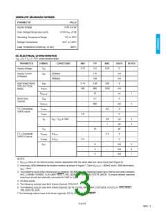
ABSOLUTE MAXIMUM RATINGS
PARAMETER
VALUE
-0.3V to 6.0V
-0.3 to VDD +0.3V
0°C to 70°C
Supply Voltage
Input Voltage Range (any input)
Operating Temperature Range
Storage Temperature
-55°C to 150°C
260°C
Lead Temperature (soldering, 10 sec)
DC ELECTRICAL CHARCTERISTICS
VDD = 5.0 V, TA = 0 - 70°C unless otherwise shown.
PARAMETER
SYMBOL
VDD
CONDITIONS
MIN
TYP
5.0
110
190
3.65
800
75
2.7
800
-
MAX
UNITS
V
NOTES
4.75
5.25
Supply Voltage
Supply Current
Unloaded
ΙDD
270Mb/s
-
-
mA
mA
V
540Mb/s
-
-
High Speed Serial
Data and Clock
Inputs
VCM
VDIFFIN
RPULLUP
VCM
3.14
3.95
450
1250
mV
Ω
-
-
1
2
Serial Data
Outputs
-
-
V
VDIFFOUT
VILMAX
VIHMIN
ΙIN
-
-
mV
V
TTL Compatible
CMOS Inputs
-
0.8
2.0
-
-
V
VIN = VDD or GND
-
-
150
µA
µA
pF
V
3
4
-
-
1
CIN
-
10
-
-
TTL Compatible
CMOS Outputs
VOLMAX
VOHMIN
ΙOUT
at ΙOUT
at ΙOUT
-
0.4
2.4
-
-
-
-
-
V
-
-
-
8
mA
mA
mA
5
6
7
4
2
NOTES
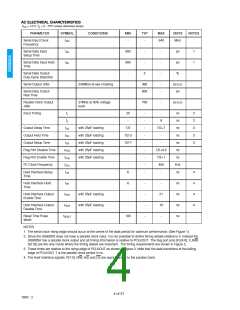
1. RPULLUP refers to the internal pullup resistor associated with the serial data and clock inputs (see Figure 4).
2. Assuming 100Ω differential termination resistor as shown in figure 7. Given VDIFFOUT = 800mV and a 100Ω termination,
ISDO = 8mA.
3. The following inputs have internal pull-up resistors: SDOMODE. The following inputs have internal pull-down resistors:
ANC_CHKSM, FLYWDIS, FLAG_MAP, RESET, CRC_MODE, FIFOE/S AND HOSTIF_MODE. To ensure reliable operation
these pins should be externally connected to GND or Vcc
.
4. All other inputs.
5. The following outputs have 8mA drivers (typical): PCLKOUT
6. The following outputs have 4mA drivers (typical): S[1:0], FL[4:0], ANC_DATA, DOUT[9:0], V, F[2:0], H, FIFO_RESET,
TRS_ERR, NO_EDH
7.The following outputs have 2mA drivers (typical): P[7:0], STD[3:0], INTERRUPT
3 of 31
19922 - 3

 GENNUM [ GENNUM CORPORATION ]