4.10.4.2 Data Format Indication
The Luma and Chroma data format codes will be reported in the YDATA_FORMAT[3:0]
and CDATA_FORMAT[3:0] bits of the VIDEO_STANDARD register when the device is
operating in HD mode, (SD/HD = LOW).
In SD or DVB-ASI mode, the data format code will only appear in the
YDATA_FORMAT[3:0] bits. The CDATA_FORMAT[3:0] bits will be set to 'F '. These codes
h
represent the data formats listed in Table 4-10.
The YDATA_FORMAT[3:0] and CDATA_FORMAT[3:0] bits of the VIDEO_STANDARD
register will default to 'F ' after device reset. These bits will also default to 'F ' if the
h
h
device loses lock to the input data stream, (LOCKED = LOW), or if Data-Through mode is
enabled, (see Data Through Mode on page 39).
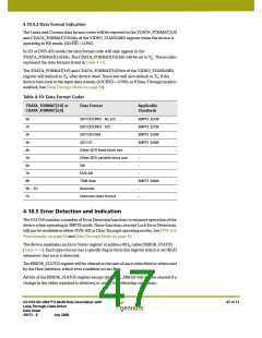
Table 4-10: Data Format Codes
YDATA_FORMAT[3:0] or
CDATA_FORMAT[3:0]
Data Format
Applicable
Standards
0h
SDTI DVCPRO - No ECC
SDTI DVCPRO - ECC
SDTI DVCAM
SMPTE 321M
1h
SMPTE 321M
2h
SMPTE 322M
3h
SDTI CP
SMPTE 326M
4h
Other SDTI fixed block size
Other SDTI variable block size
SDI
–
5h
–
6h
–
7h
DVB-ASI
–
8h
TDM data
SMPTE 346M
9h ~ Eh
Fh
Reserved
–
–
Unknown data format
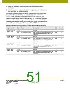
4.10.5 Error Detection and Indication
The GS1559 contains a number of Error Detection functions to enhance operation of the
device when operating in SMPTE mode. These functions, (except Lock Error Detection),
will not be available in either DVB-ASI or Data-Through operating modes. See DVB-ASI
Functionality on page 38 and Data Through Mode on page 39.
The device maintains an Error Status register at address 001 called ERROR_STATUS
h
(Table 4-11). Each type of error has a specific flag or bit in this register which is set HIGH
whenever that error is detected.
The ERROR_STATUS register will be cleared at the start of each video field or when read
by the Host Interface, which ever condition occurs first.
All bits of the ERROR_STATUS register except the LOCK_ERR bit will also be cleared if a
change in the video standard is detected, or under the following conditions:
GS1559 HD-LINX™ II Multi-Rate Deserializer with
Loop-Through Cable Driver
Data Sheet
47 of 71
30572 - 8
July 2008

 GENNUM [ GENNUM CORPORATION ]