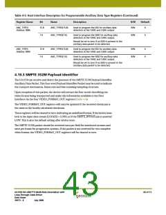
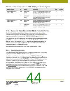
Table 4-6: Host Interface Description for SMPTE 352M Payload Identifier Registers
Register Name
Bit
Name
Description
R/W
Default
VIDEO_FORMAT_OUT_B
Address: 00Dh
15-8
SMPTE352M
Byte 4
Data will be available in this register when
Video Payload Identification Packets are
detected in the data stream.
R
0
7-0
SMPTE352M
Byte 3
Data will be available in this register when
Video Payload Identification Packets are
detected in the data stream.
R
R
R
0
0
0
VIDEO_FORMAT_OUT_A
Address: 00Ch
15-8
7-0
SMPTE352M
Byte 2
Data will be available in this register when
Video Payload Identification Packets are
detected in the data stream.
SMPTE352M
Byte 1
Data will be available in this register when
Video Payload Identification Packets are
detected in the data stream.
4.10.4 Automatic Video Standard and Data Format Detection
The GS1559 can independently detect the input video standard and data format by
using the timing parameters extracted from the received TRS ID words. This information
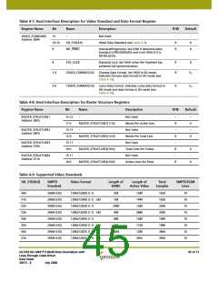
is presented to the Host Interface via the VIDEO_STANDARD register (Table 4-7).
Total samples per line, active samples per line, total lines per field/frame and active lines
per field/frame are also calculated and presented to the Host Interface via the
RASTER_STRUCTURE registers (Table 4-8). These line and sample count registers are
updated once per frame at the end of line 12. This is in addition to the information
contained in the VIDEO_STANDARD register.
After device reset, the four RASTER_STRUCTURE registers default to zero.
4.10.4.1 Video Standard Indication
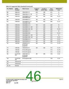
The video standard codes reported in the VD_STD[4:0] bits of the VIDEO_STANDARD
register represent the SMPTE standards as shown in Table 4-9.
In addition to the 5-bit video standard code word, the VIDEO_STANDARD register also
contains two status bits. The STD_LOCK bit will be set HIGH whenever the Flywheel has
achieved full synchronization. The INT_PROG bit will be set LOW if the detected video
standard is progressive and HIGH if the detected video standard is interlaced.
The VD_STD[4:0], STD_LOCK and INT_PROG bits of the VIDEO_STANDARD register
will default to zero after device reset. The VD_STD[4:0] and INT_PROG bits will also
default to zero if the device loses lock to the input data stream, (LOCKED = LOW), or if
the SMPTE_BYPASS pin is asserted LOW. The STD_LOCK bit will retain its previous
value if the input is removed.
GS1559 HD-LINX™ II Multi-Rate Deserializer with
Loop-Through Cable Driver
Data Sheet
44 of 71
30572 - 8
July 2008

 GENNUM [ GENNUM CORPORATION ]