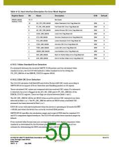
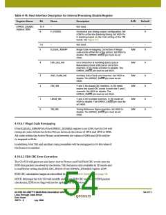
Table 4-12: Host Interface Description for Error Mask Register
Register Name
Bit
Name
Description
R/W
Default
ERROR_MASK
Address: 01Ah
15-11
–
Not Used.
–
–
0
0
0
0
0
0
0
0
0
0
0
10
9
8
7
6
5
4
3
2
1
0
VD_STD_ERR_MASK
FF_CRC_ERR_MASK
AP_CRC_ERR_MASK
LOCK_ERR_MASK
CCS_ERR_MASK
YCS_ERR_MASK
CCRC_ERR_MASK
YCRC_ERR_MASK
LNUM_ERR_MASK
SAV_ERR_MASK
EAV_ERR_MASK
Video Standard Error Flag Mask bit.
Full Field CRC Error Flag Mask bit.
Active Picture CRC Error Flag Mask bit.
Lock Error Flag Mask bit.
R/W
R/W
R/W
R/W
R/W
R/W
R/W
R/W
R/W
R/W
R/W
Chroma Checksum Error Flag Mask bit.
Luma Checksum Error Flag Mask bit.
Chroma CRC Error Flag Mask bit.
Luma CRC Error Flag Mask bit.
Line Number Error Flag Mask bit.
Start of Active Video Error Flag Mask bit.
End of Active Video Error Flag Mask bit.
4.10.5.1 Video Standard Error Detection
If a mismatch between the received SMPTE 352M packets and the calculated video
standard occurs, the GS1559 will indicate a video standard error by setting the
VD_STD_ERR bit of the ERROR_STATUS register HIGH.
4.10.5.2 EDH CRC Error Detection
The GS1559 calculates Full Field (FF) and Active Picture (AP) CRC words according to
SMPTE RP165 in support of Error Detection and Handling packets in SD signals.
These calculated CRC values are compared with the received CRC values. If a mismatch
is detected, the error is flagged in the AP_CRC_ERR and/or FF_CRC_ERR bits of the
ERROR_STATUS register. These two flags are shared between fields 1 and 2.
The AP_CRC_ERR bit will be set HIGH when an active picture CRC mismatch has been
detected in field 1 or 2. The FF_CRC_ERR bit will be set HIGH when a full field CRC
mismatch has been detected in field 1 or 2.
EDH CRC errors will only be indicated when the device is operating in SD mode (SD/HD
= HIGH), and when the device has correctly received EDH packets.
SMPTE RP165 specifies the calculation ranges and scope of EDH data for standard 525
and 625 component digital interfaces. The GS1559 will utilize these standard ranges by
default.
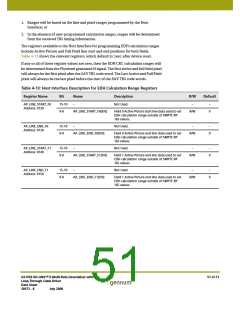
If the received video format does not correspond to 525 or 625 digital component video
standards as determined by the Flywheel pixel and line counters, then one of two
schemes for determining the EDH calculation ranges will be employed:
GS1559 HD-LINX™ II Multi-Rate Deserializer with
Loop-Through Cable Driver
Data Sheet
50 of 71
30572 - 8
July 2008

 GENNUM [ GENNUM CORPORATION ]