4.9 Data Through Mode
The GS1559 may be configured by the application layer to operate as a simple
serial-to-parallel converter. In this mode, the device presents data to the output data bus
without performing any decoding, descrambling or word-alignment.
Data-Through mode is enabled only when the MASTER/SLAVE, SMPTE_BYPASS, and
DVB_ASI input pins are set LOW. Under these conditions, the lock detection algorithm
enters PLL Lock mode, (see Lock Detect on page 29), such that the device may reclock
data not conforming to SMPTE or DVB-ASI streams. The LOCKED pin will indicate
analog lock.
When operating in Master mode, the GS1559 will set the SMPTE_BYPASS signal to logic
LOW if presented with a data stream without SMPTE TRS ID words. The LOCKED and
data bus outputs will be forced LOW and the serial digital loop-through output will be a
buffered version of the input.
4.10 Additional Processing Functions
The GS1559 contains an additional Data Processing block which is available in SMPTE
mode only, (see SMPTE Functionality on page 31).
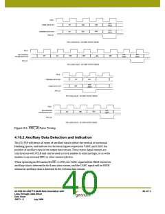
4.10.1 FIFO Load Pulse
To aid in the application-specific implementation of auto-phasing and line
synchronization functions, the GS1559 will generate a FIFO load pulse to reset
line-based FIFO storage.
The FIFO_LD output pin will normally be HIGH but will go LOW for one PCLK period,
thereby generating a FIFO write reset signal.
The FIFO load pulse will be generated such that it is co-timed to the SAV XYZ code word
presented to the output data bus. This ensures that the next PCLK cycle will correspond
to the first active sample of the video line.
Figure 4-5 shows the timing relationship between the FIFO_LD signal and the output
video data.
GS1559 HD-LINX™ II Multi-Rate Deserializer with
Loop-Through Cable Driver
Data Sheet
39 of 71
30572 - 8
July 2008

 GENNUM [ GENNUM CORPORATION ]