Thermal
8
7
6
5
4
3
2
1
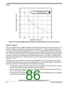
Thermalloy #2328B Pin-fin Heat Sink
(25 × 28 × 15 mm)
0
0.5
1
1.5
Approach Air Velocity (m/s)
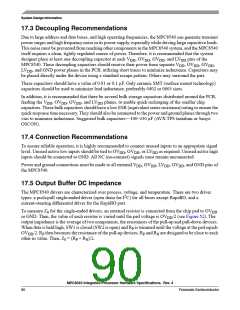
Figure 48. Thermalloy #2328B Heat Sink-to-Ambient Thermal Resistance Versus Airflow Velocity
2
2.5
3
3.5
16.2.4.2 Case 2
Every system application has different conditions that the thermal management solution must solve. As an
alternate example, assume that the air reaching the component is 85 C with an approach velocity of 1
m/sec. For a maximum junction temperature of 105 C at 7 W, the total thermal resistance of junction to
case thermal resistance plus thermal interface material plus heat sink thermal resistance must be less than
2.8 C/W. The value of the junction to case thermal resistance in Table 59 includes the thermal interface
resistance of a thin layer of thermal grease as documented in footnote 4 of the table. Assuming that the
heat sink is flat enough to allow a thin layer of grease or phase change material, then the heat sink must be
less than 2 C/W.
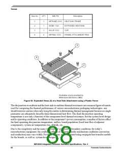
Millennium Electronics (MEI) has tooled a heat sink MTHERM-1051 for this requirement assuming a
compactPCI environment at 1 m/sec and a heat sink height of 12 mm. The MEI solution is illustrated in
Figure 49 and Figure 50. This design has several significant advantages:
•
•
•
The heat sink is clipped to a plastic frame attached to the application board with screws or plastic
inserts at the corners away from the primary signal routing areas.
The heat sink clip is designed to apply the force holding the heat sink in place directly above the
die at a maximum force of less than 10 lbs.
For applications with significant vibration requirements, silicone damping material can be applied
between the heat sink and plastic frame.
MPC8540 Integrated Processor Hardware Specifications, Rev. 4
86
Freescale Semiconductor

 FREESCALE [ Freescale ]