Thermal
Thermagon Inc.
888-246-9050
4707 Detroit Ave.
Cleveland, OH 44102
Internet: www.thermagon.com
16.2.4 Heat Sink Selection Examples
The following section provides a heat sink selection example using one of the commercially available heat
sinks.
16.2.4.1 Case 1
For preliminary heat sink sizing, the die-junction temperature can be expressed as follows:
T = T + T + (θ + θ
+ θ ) × P
SA D
J
I
R
JC
INT
where
T is the die-junction temperature
J
T is the inlet cabinet ambient temperature
I
T is the air temperature rise within the computer cabinet
R
θ
θ
θ
is the junction-to-case thermal resistance
JC
is the adhesive or interface material thermal resistance
INT
is the heat sink base-to-ambient thermal resistance
SA
P is the power dissipated by the device
D
During operation the die-junction temperatures (T ) should be maintained within the range specified in
J
Table 2. The temperature of air cooling the component greatly depends on the ambient inlet air temperature
and the air temperature rise within the electronic cabinet. An electronic cabinet inlet-air temperature (T )
A
may range from 30° to 40°C. The air temperature rise within a cabinet (T ) may be in the range of 5° to
R
10°C. The thermal resistance of some thermal interface material (θ ) may be about 1°C/W. Assuming a
INT
T of 30 C, a T of 5 C, a FC-PBGA package θ = 0.8, and a power consumption (P ) of 7.0 W, the
I
R
JC
D
following expression for T is obtained:
J
Die-junction temperature: T = 30°C + 5°C + (0.8°C/W + 1.0°C/W + θ ) × 7.0 W
J
SA
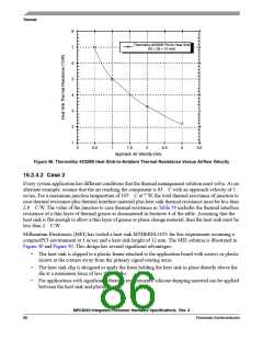
The heat sink-to-ambient thermal resistance (θ ) versus airflow velocity for a Thermalloy heat sink
SA
#2328B is shown in Figure 48.
Assuming an air velocity of 2 m/s, we have an effective θ
of about 3.3 C/W, thus
SA+
T = 30 C + 5 C + (0.8 C/W +1.0 C/W + 3.3 C/W) × 7.0 W,
J
resulting in a die-junction temperature of approximately 71 C which is well within the maximum
operating temperature of the component.
MPC8540 Integrated Processor Hardware Specifications, Rev. 4
Freescale Semiconductor
85

 FREESCALE [ Freescale ]