RESET Initialization
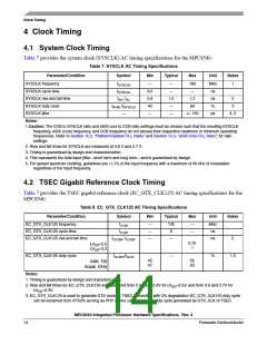
4.3 RapidIO Transmit Clock Input Timing
Table 9 provides the RapidIO transmit clock input (RIO_TX_CLK_IN) AC timing specifications for the
MPC8540.
Table 9. RIO_TX_CLK_IN AC Timing Specifications
Parameter/Condition
Symbol
Min
Typical
Max
Unit
Notes
RIO_TX_CLK_IN frequency
RIO_TX_CLK_IN cycle time
RIO_TX_CLK_IN duty cycle
Notes:
fRCLK
tRCLK
125
—
—
—
—
—
8
MHz
ns
tRCLKH/tRCLK
48
52
%
1
1. Requires ±100 ppm long term frequency stability. Timing is guaranteed by design and characterization.
4.4 Real Time Clock Timing
Table 10 provides the real time clock (RTC) AC timing specifications for the MPC8540.
Table 10. RTC AC Timing Specifications
Parameter/Condition
RTC clock high time
Symbol
Min
Typical
Max
Unit
Notes
tRTCH
2 x
—
—
ns
tCCB_CLK
RTC clock low time
tRTCL
2 x
—
—
ns
tCCB_CLK
5 RESET Initialization
This section describes the AC electrical specifications for the RESET initialization timing requirements of
the MPC8540. Table 7 provides the RESET initialization AC timing specifications for the MPC8540.
Table 11. RESET Initialization Timing Specifications
Parameter/Condition
Min
Max
Unit
Notes
Required assertion time of HRESET
Minimum assertion time for SRESET
100
512
100
—
—
—
μs
SYSCLKs
μs
1
PLL input setup time with stable SYSCLK before
HRESET negation
Input setup time for POR configs (other than PLL config)
with respect to negation of HRESET
4
2
—
—
SYSCLKs
SYSCLKs
1
1
Input hold time for POR configs (including PLL config)
with respect to negation of HRESET
MPC8540 Integrated Processor Hardware Specifications, Rev. 4
Freescale Semiconductor
15

 FREESCALE [ Freescale ]