Freescale Semiconductor, Inc.
SECTION 6 PARALLEL INPUT/OUTPUT
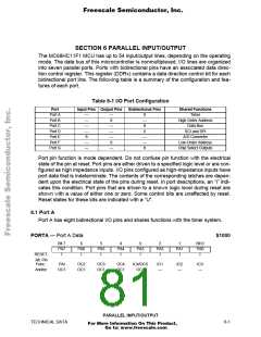
The MC68HC11F1 MCU has up to 54 input/output lines, depending on the operating
mode. The data bus of this microcontroller is nonmultiplexed. I/O lines are organized
into seven parallel ports. Ports with bidirectional pins have an associated data direc-
tion control register. This register (DDRx) contains a data direction control bit for each
bidirectional port line. The following table is a summary of the configuration and fea-
tures of each port.
Table 6-1 I/O Port Configuration
Port
Input Pins Output Pins
Bidirectional Pins
Shared Functions
Timer
Port A
Port B
Port C
Port D
Port E
Port F
Port G
—
—
—
—
8
—
8
8
—
8
High-Order Address
Data Bus
—
—
—
8
6
SCI and SPI
—
—
8
A/D Converter
Low-Order Address
Chip Select Outputs
—
—
—
Port pin function is mode dependent. Do not confuse pin function with the electrical
state of the pin at reset. Port pins are either driven to a specified logic level or are con-
figured as high impedance inputs. I/O pins configured as high-impedance inputs have
port data that is indeterminate. The contents of the corresponding latches are depen-
dent upon the electrical state of the pins during reset. In port descriptions, an “I” indi-
cates this condition. Port pins that are driven to a known logic level during reset are
shown with a value of either one or zero. Some control bits are unaffected by reset.
Reset states for these bits are indicated with a “U”.
6.1 Port A
Port A has eight bidirectional I/O pins and shares functions with the timer system.
PORTA — Port A Data
$1000
Bit 7
PA7
I
6
PA6
I
5
PA5
I
4
PA4
I
3
PA3
I
2
PA2
I
1
PA1
I
Bit 0
PA0
I
RESET:
Alt. Pin
Func.:
PAI
OC2
OC1
OC3
OC1
OC4
OC1
IC4/OC5
OC1
IC1
—
IC2
—
IC3
—
And/or:
OC1
PARALLEL INPUT/OUTPUT
TECHNICAL DATA
6-1
For More Information On This Product,
Go to: www.freescale.com

 FREESCALE [ Freescale ]