Freescale Semiconductor, Inc.
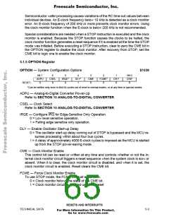
5.1.3 Computer Operating Properly (COP) Reset
The MCU includes a COP system to help protect against software failures. When the
COP is enabled, the software is responsible for keeping a free-running watchdog timer
from timing out. When the software is no longer being executed in the intended se-
quence, a system reset is initiated.
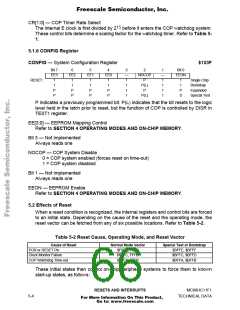
The state of the NOCOP bit in the CONFIG register determines whether the COP sys-
tem is enabled or disabled. To change the enable status of the COP system, change
the contents of the CONFIG register and then perform a system reset. In the special
test and bootstrap operating modes, the COP system is initially inhibited by the disable
resets (DISR) control bit in the TEST1 register. The DISR bit can subsequently be writ-
ten to zero to enable COP resets.
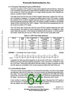
The COP timer rate control bits CR[1:0] in the OPTION register determine the COP
time-out period. The system E clock is divided by the values shown in Table 5-1. After
reset, these bits are zero, which selects the fastest time-out period. In normal operat-
ing modes, these bits can only be written once within 64 bus cycles after reset.
Table 5-1 COP Timer Rate Selection
CR[1:0]
Divide
E By
XTAL = 8.0 MHz Time-
out
XTAL = 12.0 MHz
Time-out
XTAL = 16.0 MHz
Time-out
–0 ms, +16.4 ms
–0 ms, +10.9 ms
–0 ms, +8.2 ms
15
2
0 0
0 1
1 0
1 1
16.384 ms
65.536 ms
262.14 ms
1.049 s
10.923 ms
43.691 ms
174.76 ms
699.05 ms
3.0 MHz
8.192 ms
32.768 ms
131.07 ms
524.29 ms
4.0 MHz
17
2
19
2
21
2
E =
2.0 MHz
COPRST — Arm/Reset COP Timer Circuitry
$103A
Bit 7
6
6
0
5
5
0
4
4
0
3
3
0
2
2
0
1
1
0
Bit 0
7
0
0
0
RESET:
Complete the following reset sequence to service the COP timer. Write $55 to CO-
PRST to arm the COP timer clearing mechanism. Then write $AA to COPRST to clear
the COP timer. Performing instructions between these two steps is possible as long
as both steps are completed in the correct sequence before the timer times out.
5.1.4 Clock Monitor Reset
The clock monitor circuit is based on an internal RC time delay. If no MCU clock edges
are detected within this RC time delay, the clock monitor can optionally generate a sys-
tem reset. The clock monitor function is enabled or disabled by the CME and FCME
control bits in the OPTION register. The presence of a time-out is determined by the
RC delay, which allows the clock monitor to operate without any MCU clocks.
Clock monitor is used as a backup for the COP system. Because the COP needs a
clock to function, it is disabled when the clocks stop. Therefore, the clock monitor sys-
tem can detect clock failures not detected by the COP system.
RESETS AND INTERRUPTS
MC68HC11F1
5-2
TECHNICAL DATA
For More Information On This Product,
Go to: www.freescale.com

 FREESCALE [ Freescale ]