Electrical Characteristics
A.1.10 Supply Currents
This section describes the current consumption characteristics of the device as well as the conditions for
the measurements.
A.1.10.1 Measurement Conditions
Run current is measured on VDDR pin. It does not include the current to drive external loads. Unless
otherwise noted the currents are measured in special single chip mode and the CPU code is executed from
RAM. For Run and Wait current measurements PLL is on and the reference clock is the IRC1M trimmed
to 1MHz. The bus frequency is 32MHz and the CPU frequency is 64MHz. Table A-8., Table A-9. and
Table A-10. show the configuration of the CPMU module and the peripherals for Run, Wait and Stop
current measurement.
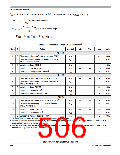
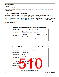
Table A-8. CPMU Configuration for Pseudo Stop Current Measurement
CPMU REGISTER
Bit settings/Conditions
PLLSEL=0, PSTP=1,
CPMUCLKS
PRE=PCE=RTIOSCSEL=COPOSCSEL=1
OSCE=1, External Square wave on EXTAL f
=16MHz,
EXTAL
CPMUOSC
V = 1.8V, V =0V
IH
IL
CPMURTI
RTDEC=0, RTR[6:4]=111, RTR[3:0]=1111;
WCOP=1, CR[2:0]=111
CPMUCOP
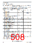
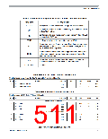
Table A-9. CPUM Configuration for Run/Wait and Full Stop Current Measurement
CPMU REGISTER
CPMUSYNR
Bit settings/Conditions
VCOFRQ[1:0]=01,SYNDIV[5:0] = 32
POSTDIV[4:0]=0,
CPMUPOSTDIV
CPMUCLKS
PLLSEL=1
OSCE=0,
Reference clock for PLL is f =f
CPMUOSC
trimmed to 1MHz
ref irc1m
API settings for STOP current measurement
APIEA=0, APIFE=1, APIE=0
trimmed to 10Khz
CPMUAPICTL
CPMUAPITR
CPMUAPIRH/RL
set to $FFFF
S12P-Family Reference Manual, Rev. 1.13
510
Freescale Semiconductor

 FREESCALE [ Freescale ]