Electrical Characteristics
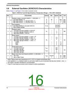
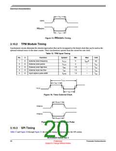
tIHIL
KBIPx
IRQ/KBIPx
tILIH
Figure 15. IRQ/KBIPx Timing
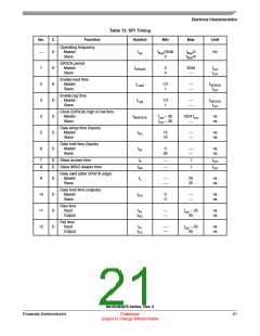
3.10.2 TPM Module Timing
Synchronizer circuits determine the shortest input pulses that can be recognized or the fastest clock that can be used as the
optional external source to the timer counter. These synchronizers operate from the current bus rate clock.
Table 12. TPM Input Timing
No.
C
Function
Symbol
Min
Max
Unit
1
2
3
4
5
D
D
D
D
D
External clock frequency
External clock period
fTCLK
tTCLK
tclkh
0
fBus/4
—
Hz
tcyc
tcyc
tcyc
tcyc
4
External clock high time
External clock low time
Input capture pulse width
1.5
1.5
1.5
—
tclkl
—
tICPW
—
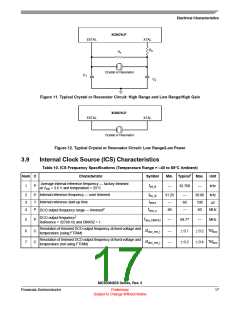
tTCLK
tclkh
TCLK
tclkl
Figure 16. Timer External Clock
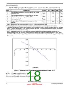
tICPW
TPMCHn
TPMCHn
tICPW
Figure 17. Timer Input Capture Pulse
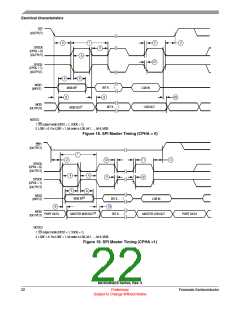
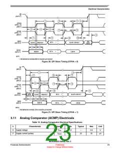
3.10.3 SPI Timing
Table 13 and Figure 18 through Figure 21 describe the timing requirements for the SPI system.
MC9S08QE8 Series, Rev. 3
20
Preliminary
Freescale Semiconductor
Subject to Change Without Notice

 FREESCALE [ Freescale ]