Configuration Register (CONFIG)
5.3 Configuration Register
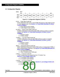
Address:
$001F
Bit 7
6
5
4
INDEP
0
3
LVIRST
1
2
LVIPWR
1
1
STOPE
0
Bit 0
COPD
0
Read:
Write:
Reset:
EDGE
0
BOTNEG TOPNEG
0
0
Figure 5-1. Configuration Register (CONFIG)
EDGE — Edge-Align Enable Bit
EDGE determines if the motor control PWM will operate in edge-aligned mode
or center-aligned mode. See Section 12. Pulse-Width Modulator for Motor
Control (PWMMC).
1 = Edge-aligned mode enabled
0 = Center-aligned mode enabled
BOTNEG — Bottom-Side PWM Polarity Bit
BOTNEG determines if the bottom-side PWMs will have positive or negative
polarity. See Section 12. Pulse-Width Modulator for Motor Control
(PWMMC).
1 = Negative polarity
0 = Positive polarity
TOPNEG — Top-Side PWM Polarity Bit
TOPNEG determines if the top-side PWMs will have positive or negative
polarity. See Section 12. Pulse-Width Modulator for Motor Control
(PWMMC).
1 = Negative polarity
0 = Positive polarity
INDEP — Independent Mode Enable Bit
INDEP determines if the motor control PWMs will be six independent PWMs or
three complementary PWM pairs. See Section 12. Pulse-Width Modulator for
Motor Control (PWMMC).
1 = Six independent PWMs
0 = Three complementary PWM pairs
LVIRST — LVI Reset Enable Bit
LVIRST enables the reset signal from the LVI module. See
Section 9. Low-Voltage Inhibit (LVI).
1 = LVI module resets enabled
0 = LVI module resets disabled
LVIPWR — LVI Power Enable Bit
LVIPWR enables the LVI module. See Section 9. Low-Voltage Inhibit (LVI).
1 = LVI module power enabled
0 = LVI module power disabled
Data Sheet
80
MC68HC908MR32 • MC68HC908MR16 — Rev. 6.0
Configuration Register (CONFIG)
MOTOROLA

 FREESCALE [ Freescale ]