Computer Operating Properly (COP)
Addr.
Register Name
Bit 7
6
5
4
3
2
1
Bit 0
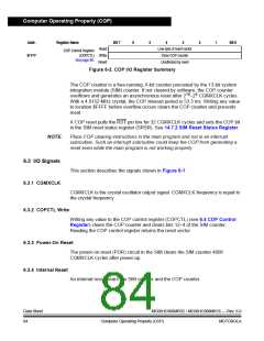
Read:
(COPCTL) Write:
See page 85.
Low byte of reset vector
Clear COP counter
Unaffected by reset
COP Control Register
$FFFF
Reset:
Figure 6-2. COP I/O Register Summary
The COP counter is a free-running, 6-bit counter preceded by the 13-bit system
integration module (SIM) counter. If not cleared by software, the COP counter
overflows and generates an asynchronous reset after 218–24 CGMXCLK cycles.
With a 4.9152-MHz crystal, the COP timeout period is 53.3 ms. Writing any value
to location $FFFF before overflow occurs clears the COP counter and prevents
reset.
A COP reset pulls the RST pin low for 32 CGMXCLK cycles and sets the COP bit
in the SIM reset status register (SRSR). See 14.7.2 SIM Reset Status Register.
NOTE:
Place COP clearing instructions in the main program and not in an interrupt
subroutine. Such an interrupt subroutine could keep the COP from generating a
reset even while the main program is not working properly.
6.3 I/O Signals
6.3.1 CGMXCLK
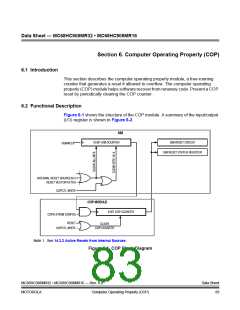
This section describes the signals shown in Figure 6-1.
CGMXCLK is the crystal oscillator output signal. CGMXCLK frequency is equal to
the crystal frequency.
6.3.2 COPCTL Write
Writing any value to the COP control register (COPCTL) (see 6.4 COP Control
Register) clears the COP counter and clears bits 12–4 of the SIM counter.
Reading the COP control register returns the reset vector.
6.3.3 Power-On Reset
The power-on reset (POR) circuit in the SIM clears the SIM counter 4096
CGMXCLK cycles after power-up.
6.3.4 Internal Reset
An internal reset clears the SIM counter and the COP counter.
Data Sheet
84
MC68HC908MR32 • MC68HC908MR16 — Rev. 6.0
Computer Operating Properly (COP) MOTOROLA

 FREESCALE [ Freescale ]