Development Support
Enter monitor mode by either:
•
Executing a software interrupt instruction (SWI) or
Applying a logic 0 and then a logic 1 to the RST pin
•
Once out of reset, the MCU waits for the host to send eight security bytes. After
receiving the security bytes, the MCU sends a break signal (10 consecutive logic
0s) to the host computer, indicating that it is ready to receive a command. The
break signal also provides a timing reference to allow the host to determine the
necessary baud rate.
Monitor mode uses alternate vectors for reset and SWI. The alternate vectors are
in the $FE page instead of the $FF page and allow code execution from the internal
monitor firmware instead of user code. The computer operating properly (COP)
module is disabled in monitor mode as long as VHI is applied to either the IRQ pin
or the RST pin. (See Section 14. System Integration Module (SIM) for more
information on modes of operation.)
18.3.1.3 Forced Monitor Mode
If the voltage applied to the IRQ1 is less than VDD + VHI the MCU will come out of
reset in user mode. The MENRST module is monitoring the reset vector fetches
and will assert an internal reset if it detects that the reset vectors are erased ($FF).
When the MCU comes out of reset, it is forced into monitor mode without requiring
high voltage on the IRQ1 pin.
The COP module is disabled in forced monitor mode. Any reset other than a POR
reset will automatically force the MCU to come back to the forced monitor mode.
18.3.1.4 Data Format
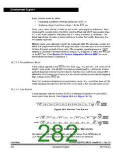
Communication with the monitor ROM is in standard non-return-to-zero (NRZ)
mark/space data format. (See Figure 18-9 and Figure 18-10.)
NEXT
START
BIT
START
BIT
STOP
BIT
BIT 0
BIT 1
BIT 2
BIT 3
BIT 4
BIT 5
BIT 6
BIT 7
Figure 18-9. Monitor Data Format
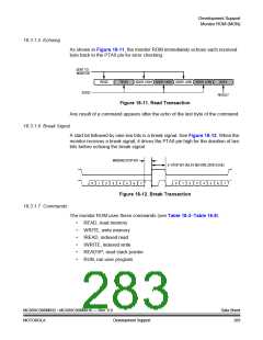
NEXT
START
BIT
START
BIT
STOP
BIT
$A5
BIT 0
BIT 1
BIT 1
BIT 2
BIT 2
BIT 3
BIT 3
BIT 4
BIT 4
BIT 5
BIT 5
BIT 6
BIT 6
BIT 7
BIT 7
STOP
BIT
START
BIT
NEXT
START
BIT
BREAK
BIT 0
Figure 18-10. Sample Monitor Waveforms
The data transmit and receive rate can be anywhere from 4800 baud to
28.8 Kbaud. Transmit and receive baud rates must be identical.
Data Sheet
282
MC68HC908MR32 • MC68HC908MR16 — Rev. 6.0
Development Support
MOTOROLA

 FREESCALE [ Freescale ]