Pulse-Width Modulator for Motor Control (PWMMC)
PWM Glossary
OUTCTL— Output Control Enable Bit
This read/write bit allows the user to manually control the PWM pins. When set,
the PWM generator is no longer the input to the dead-time and output circuitry.
The OUTx bits determine the state of the PWM pins. Setting the OUTCTL bit
does not disable the PWM generator. The generator continues to run, but is no
longer the input to the PWM dead-time and output circuitry. When OUTCTL is
cleared, the outputs of the PWM generator immediately become the inputs to
the dead-time and output circuitry.
1 = PWM outputs controlled manually
0 = PWM outputs determined by PWM generator
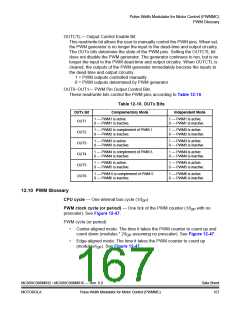
OUT6–OUT1— PWM Pin Output Control Bits
These read/write bits control the PWM pins according to Table 12-10.
Table 12-10. OUTx Bits
OUTx Bit
Complementary Mode
1 — PWM1 is active.
Independent Mode
1 — PWM1 is active.
0 — PWM1 is inactive.
OUT1
0 — PWM1 is inactive.
1 — PWM2 is complement of PWM 1.
0 — PWM2 is inactive.
1 — PWM2 is active.
0 — PWM2 is inactive.
OUT2
OUT3
OUT4
OUT5
OUT6
1 — PWM3 is active.
0 — PWM3 is inactive.
1 — PWM3 is active.
0 — PWM3 is inactive.
1 — PWM4 is complement of PWM 3.
0 — PWM4 is inactive.
1 — PWM4 is active.
0 — PWM4 is inactive.
1 — PWM5 is active.
0 — PWM5 is inactive.
1 — PWM5 is active.
0 — PWM5 is inactive.
1 — PWM 6 is complement of PWM 5.
0 — PWM6 is inactive.
1 — PWM6 is active.
0 — PWM6 is inactive.
12.10 PWM Glossary
CPU cycle — One internal bus cycle (1/fOP
)
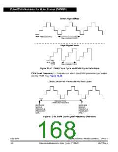
PWM clock cycle (or period) — One tick of the PWM counter (1/fOP with no
prescaler). See Figure 12-47.
PWM cycle (or period)
•
Center-aligned mode: The time it takes the PWM counter to count up and
count down (modulus * 2/fOP assuming no prescaler). See Figure 12-47.
•
Edge-aligned mode: The time it takes the PWM counter to count up
(modulus/fOP). See Figure 12-47.
MC68HC908MR32 • MC68HC908MR16 — Rev. 6.0
MOTOROLA Pulse-Width Modulator for Motor Control (PWMMC)
Data Sheet
167

 FREESCALE [ Freescale ]