System Design Information
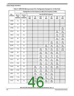
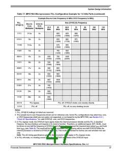
Table 17. MPC7455 Microprocessor PLL Configuration Example for 1.0 GHz Parts (continued)
Example Bus-to-Core Frequency in MHz (VCO Frequency in MHz)
PLL_
CFG[0:4]
Bus (SYSCLK) Frequency
Bus-to-
Core
Multiplier Multiplier
Core-to-
VCO
33.3
MHz
50
MHz
66.6
MHz
75
MHz
83
MHz
100
133
MHz
MHz
11111
01011
11100
11001
00011
11011
00001
00101
00111
01001
01101
11101
12.5x
13x
13.5x
14x
15x
16x
17x
18x
20x
21x
24x
28x
2x
2x
2x
2x
2x
2x
2x
2x
2x
2x
2x
2x
600
(1200)
833
(1666)
938
(1876)
650
(1300)
865
(1730)
975
(1950)
675
(1350)
900
(1800)
700
(1400)
933
(1866)
500
(1000)
750
(1500)
1000
(2000)
533
(1066)
800
(1600)
566
(1132)
850
(1900)
600
(1200)
900
(1800)
667
(1334)
1000
(2000)
700
(1400)
800
(1600)
933
(1866)
00110
11110
PLL bypass
PLL off
PLL off, SYSCLK clocks core circuitry directly
PLL off, no core clocking occurs
Notes:
1. PLL_CFG[0:4] settings not listed are reserved.
2. The sample bus-to-core frequencies shown are for reference only. Some PLL configurations may select bus, core,
or VCO frequencies which are not useful, not supported, or not tested for by the MPC7455; see Section 5.2.1,
“Clock AC Specifications,” for valid SYSCLK, core, and VCO frequencies.
3. In PLL-bypass mode, the SYSCLK input signal clocks the internal processor directly and the PLL is disabled.
However, the bus interface unit requires a 2x clock to function. Therefore, an additional signal, EXT_QUAL, must
be driven at one-half the frequency of SYSCLK and offset in phase to meet the required input setup t
and hold
IVKH
time t
(see Table 9). The result will be that the processor bus frequency will be one-half SYSCLK while the
IXKH
internal processor is clocked at SYSCLK frequency. This mode is intended for factory use and emulator tool use
only.
Note: The AC timing specifications given in this document do not apply in PLL-bypass mode.
4. In PLL-off mode, no clocking occurs inside the MPC7455 regardless of the SYSCLK input.
MPC7455 RISC Microprocessor Hardware Specifications, Rev. 4.1
Freescale Semiconductor
47

 FREESCALE [ Freescale ]