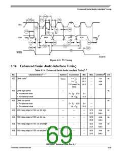
Enhanced Serial Audio Interface Timing
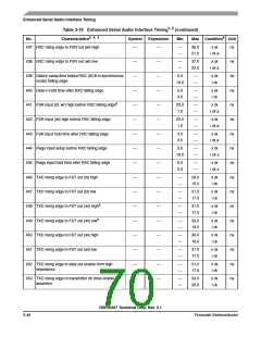
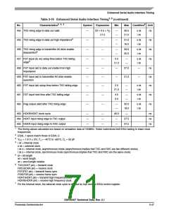
Table 3-19 Enhanced Serial Audio Interface Timing1, 2 (continued)
No.
Characteristics3, 4, 5
Symbol
Expression
Min
Max Condition6 Unit
454 TXC rising edge to data out valid
—
23 + 0.5 × T
—
—
26.5
21.0
x ck
i ck
ns
ns
ns
ns
C
21.0
455 TXC rising edge to data out high impedance9
—
—
—
—
—
—
—
—
31.0
16.0
x ck
i ck
456 TXC rising edge to transmitter #0 drive enable
deassertion9
—
—
34.0
20.0
x ck
i ck
457 FST input (bl, wr) setup time before TXC falling
edge8
2.0
—
—
x ck
i ck
21.0
458 FST input (wl) to data out enable from high
impedance
—
—
—
—
—
—
—
27.0
—
ns
ns
ns
459 FST input (wl) to transmitter #0 drive enable
assertion
—
31.0
—
460 FST input (wl) setup time before TXC falling edge
461 FST input hold time after TXC falling edge
462 Flag output valid after TXC rising edge
2.0
—
—
x ck
i ck
21.0
—
—
—
—
4.0
0.0
—
—
x ck
i ck
ns
ns
—
—
32.0
18.0
x ck
i ck
463 HCKR/HCKT clock cycle
—
—
—
—
—
—
40.0
—
—
ns
ns
ns
464 HCKT input rising edge to TXC output
465 HCKR input rising edge to RXC output
27.5
27.5
—
1
The timing values calculated are based on simulation data at 150MHz. Tester restrictions limit ESAI testing to lower clock
frequencies.
2
3
4
ESAI_1 specs match those of ESAI_0.
VCC = 1.8 V 5%; TJ = –40°C to +95°C, CL = 50 pF
i ck = internal clock
x ck = external clock
i ck a = internal clock, asynchronous mode (asynchronous implies that TXC and RXC are two different clocks)
i ck s = internal clock, synchronous mode (synchronous implies that TXC and RXC are the same clock)
5
6
bl = bit length
wl = word length
wr = word length relative
TXC(SCKT pin) = transmit clock
RXC(SCKR pin) = receive clock
FST(FST pin) = transmit frame sync
FSR(FSR pin) = receive frame sync
HCKT(HCKT pin) = transmit high frequency clock
HCKR(HCKR pin) = receive high frequency clock
7
For the internal clock, the external clock cycle is defined by Icyc and the ESAI control register.
DSP56367 Technical Data, Rev. 2.1
Freescale Semiconductor
3-47

 FREESCALE [ Freescale ]